


Single and Dual Input Analyzers for Low Level Conductivity
AX410, AX411, AX413, AX416, AX418, AX450, AX455 & AX456
6 INSTALLATION
IM/AX4CO Issue 11
59
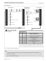
6.5.2 Connections
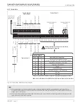
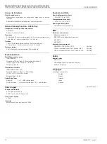
Fig. 6.11 Connections, Panel-mount Analyzers
Note.
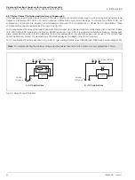
When connecting non-metal conductivity cells or metal conductivity cells that are isolated from earth (ground), e.g.
mounted in plastic pipework, link Terminal B14 (and Terminal B6 if dual input analyzer) to the earth (ground) stud on the
analyzer case - see Fig. 6.10.
When connecting earthed (grounded) metal conductivity cells, ensure that the cell earth (ground) and the analyzer earth
(ground) stud are at the same potential.
Refer also to Section 6.6 for ABB UK and US Sensor Systems Connections
* When a 2-wire Pt100, Pt1000 or 'balco 3k' temperature compensator is fitted.
Terminal Block B
Conductivity Cell Connections
Sensor B
Sensor A
B1
B9
Temperature Compensator Common.
Link B9 to B10 (and B1 to B2 if Dual Input Analyzer) *
B2
B10
Temperature Compensator Third Lead
B3
B11
Temperature Compensator
B4
B12
Screen
B5
B13
Cell (Cell Electrode)
B6
B14
Cell (Earth Electrode) – see Note below
B7
B15
Not Used
B8
B16
Not Used
L
Line
N
Neutral
E
Connect supply earth (ground) to stud on case
A4 C
A5 NC Relay 1
A6 NO
A7 C
A8 NC Relay 2
A9 NO
A10 C
A11 NC Relay 3 (see Note 1 below)
A12 NO
A13 +
Analog Output 1
A14 —
A15 +
Analog Output 2
A16 —
Terminal Block B
Terminal block A
Temperature Compensator
Connections
Common
Link
TC
B1
B2
B3
B4
B5
B6
B7
B8
B9
B10
B11
B12
B13
B14
B15
B16
Common
Link
TC
Temperature Compensator
Connections
Terminal Block C
(Option Board)
C1
Not Used
C2
Not Used
C3
C4
C5
C6
Not Used
C7
C
C8
NC
Relay 4
C9
NO
C10 C
C11 NC
Relay 5
C12 NO
C13 +
Analog Output 3
C14 —
C15 +
Analog Output 4
C16 —
Earth (Ground)
Stud on Case
(see Fig. 6.10)
Used for optional
RS485 connection.
Refer to IM/PROBUS
85 to 265 V AC + 12
or
to
Power
24 V AC
–
24V DC Supplies
Before making any electrical
connections, see Warnings
on page 53


