


Single and Dual Input Analyzers for Low Level Conductivity
AX410, AX411, AX413, AX416, AX418, AX450, AX455 & AX456
5 PROGRAMMING
32
IM/AX4CO Issue 11
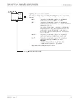
USP Offset
Enables the USP645 alarm set point value to be adjusted for increased process
protection, i.e. the USP alarm set point value in Table 5.3 is offset by the amount
entered (table value - offset value) to enable the alarm to be triggered early.
Note.
The
USP Offset
parameter is available only on AX450 and AX455 analyzers and
only if
A: Cond.Units
is set to
USP645
A1: Type
is set to
USP645
.
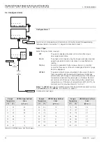
Alarm 1 Set Point
Set the alarm set point to a value within the input range being displayed - see Table 5.2
(page 22).
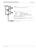
Alarm 1 Hysteresis
A differential set point can be defined between 0 and 5% of the alarm set point value.
Set the required hysteresis in 0.1% increments.
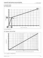
See also Fig. 5.1 to Fig. 5.5 (page 33).
Alarm 1 Delay
If an alarm condition occurs, activation of the relays and LEDs can be delayed for a
specified time period. If the alarm clears within the period, the alarm is not activated.
Set the required delay, in the range 0 to 60 seconds in 1 second increments.
See also Fig. 5.1 to Fig. 5.5 (page 33).
Alarms 2 and 3 configuration (and Alarms 4 and 5 if option board fitted
and
analog
features enabled - see section 7.3, page 62) is identical to Alarm 1.
A1: Hysteresis
0.0
%
A1: Delay
0
Secs
CONFIG. OUTPUTS
Config. Alarm 2
Config. Alarm 1
A1: Setpoint
100.0
uS/cm
A1: USP Offset
0.00
uS/cm
A1: Type
set
to
USP645
A1: Type
not
set to
USP645


