


Single and Dual Input Analyzers for Low Level Conductivity
AX410, AX411, AX413, AX416, AX418, AX450, AX455 & AX456
2 OPERATION
4
IM/AX4CO Issue 11
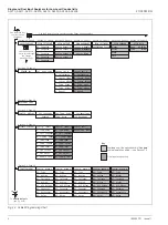
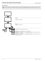
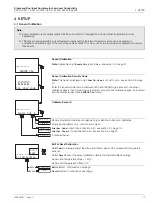
Fig. 2.3 Overall Programming Chart
To
CONFIG. OUTPUTS
(see Fig. 2.3B)
SECURITY CODE
Section 5.1, Page 19
CONFIG. DISPLAY
Set Language
Set Temp. Units
Set Backlight
LED Backlight
Temp. Units
English
Section 5.2, Page 20
Available only if the option board is fitted
and
analog features enabled — see Section 7.3
Key
Dual input analyzer only
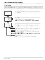
Use the Sidescroll Key to scroll through the Pages within each Menu
VIEW SETPOINTS
VIEW OUTPUTS
VIEW HARDWARE
VIEW SOFTWARE
A1: Setpoint
Analog Output 1
Sensor A Module
AX450/2000 Issue
A2: Setpoint
Analog Output 2
Sensor B Module
A3: Setpoint
Analog Output 3
Option Board
A4: Setpoint
Analog Output 4
A5: Setpoint
Use the Downscroll
Key to scroll through
the Farmes
within each Page
OPERATING PAGE
Section 2.3, Page 6
Section 3.1, Page 9
Section 3.2, Page 10 Section 3.3, Page 11 Section 3.4, Page 12
Section 3.5, Page 13 Section 3.6, Page 16
Alarms
Errors
Power
Cals
VIEW LOGBOOK
VIEW CLOCK
Date
05:02:04
Time
12:00
Use the Menu Key
to scroll through
the Menus
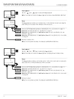
CONFIG.ALARMS
Config. Alarm 1
A1: Type
A1: Assign
A1: Failsafe
A1: Action
A1: Setpoint
A1: Hysteresis
A1: Delay
Config. Alarm 2
A2: Type
A2: Assign
A2: Failsafe
A2: Action
A2: Setpoint
A2: Hysteresis
A2: Delay
A3: Assign
A3: Failsafe
A3: Action
A3: Setpoint
A3: Hysteresis
A3: Delay
Config. Alarm 3
A3: Type
Section 5.4, Page 30
Config. Alarm 4
A4: Type
A4: Assign
A4: Failsafe
A4: Action
A4: Setpoint
A4: Hysteresis
A4: Delay
Config. Alarm 5
A5: Type
A5: Assign
A5: Failsafe
A5: Action
A5: Setpoint
A5: Hysteresis
A5: Delay
CONFIG.SENSORS
B: Cond.Units
B: Cell Constant
B: Temp.Comp.
B: Temp. Sensor
B: TDS Factor
B: TDS Units
B: Enable Cals.
Section 5.3, Page 21
Config. Sensor B
Config. Sensor A
A: Cond.Units
A: Cell Constant
A: Temp. Sensor
A: TDS Factor
A: TDS Units
A: Enable Cals.
A: Temp.Comp.
A: Temp.Coeff.
B: Temp.Coeff.
After Cat. Limit
Signal Calc
SENSOR CAL.
Cal. User Code
Section 4.1, Page 17
Sensor Cal. B
B: Calibration
B: Sensor Slope
B: Sensor Offset
B: Temp. Slope
B: Temp. Offset
B: Reset?
Sensor Cal. A
A: Calibration
A: Sensor Slope
A: Sensor Offset
A: Temp. Slope
A: Temp. Offset
A: Reset?
B: T.Comp. Range
A: T.Comp. Range
A1: USP Offset
A2: USP Offset
A3: USP Offset
A4: USP Offset
A5: USP Offset


