■
Connection procedure of the resistor cables
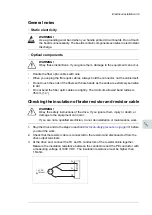
WARNING!
Obey the safety instructions of the drive. If you ignore them, injury or death, or
damage to the equipment can occur.
If you are not a qualified electrician, do not do installation or maintenance work.
1.
Stop the drive and do the steps in section
Electrical safety precautions (page 38)
before
you start the work.
2.
Open the door of the brake unit cubicle and remove the shrouding.
3.
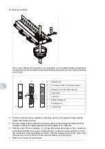
Lead the cables into the cubicle. Make the 360° earthing arrangement at the cable entry
as shown. Install the rubber grommet (if present) below the cable entry for proper sealing.
118 Electrical installation
3.
Lead the cables into the cubicle. Make the 360° earthing arrangement at the cable
entry as shown.
4.
Cut the cables to suitable length. Strip the cables and conductors.
5.
Twist the cable screens into bundles and connect the bundles to the PE busbar in the
cubicle.
6.
Connect any separate ground conductors/cables to the PE busbar in the cubicle.
7.
Connect the phase conductors to the output terminals. Use the torques specified
under
Tightening torques
(page
199
).
8.
Refit any shrouding removed earlier and close the cubicle doors.
9.
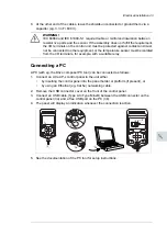
At the motor, connect the cables according to instructions from the motor
manufacturer. Pay special attention to the phase order. For minimum radio-frequency
interference, ground the cable shield 360 degrees at the lead-through of the motor
terminal box, or ground the cable by twisting the shield so that the flattened shield is
wider than 1/5 of its length.
Connecting an external brake resistor assembly
See section
Electrical installation of custom brake resistors
(page
267
).
For the location of the terminals, refer to the dimension drawings delivered with the unit or
the dimension drawing examples in chapter
Dimensions
.
a
b
b > 1/5 · a
Grommet
4.
Cut the cables to suitable length. Strip the cables and conductors.
5.
Twist the cable shields into bundles and connect the bundles to the PE busbar in the
cubicle.
6.
Connect the resistor cables. Note the connection of the third conductor and the cable
shield. See also the circuit diagrams delivered with the unit. See
Technical data
for
tightening torques.
■
Connection procedure of the thermal switch cable
WARNING!
Obey the safety instructions of the drive. If you ignore them, injury or death, or
damage to the equipment can occur.
If you are not a qualified electrician, do not do installation or maintenance work.
Ground the outer shield of the cable 360 degrees at the cabinet lead-through, for example,
as follows:
1.
Stop the drive and do the steps in section
Electrical safety precautions (page 38)
before
you start the work.
2.
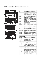
Slacken the locking screws of the entry and open it wide. Thread the cables through
the grommets below the cable entry, then into the cubicle between the cushions.
3.
Remove the outer jacket at the entry so that the cushions can press on the bare shield.
Electrical installation 41
11
Содержание ACS880-607 Series
Страница 1: ... ABB INDUSTRIAL DRIVES ACS880 607 3 phase brake units Hardware manual ...
Страница 2: ......
Страница 4: ......
Страница 8: ...8 ...
Страница 12: ...12 ...
Страница 30: ...30 ...
Страница 32: ...32 ...
Страница 36: ...36 ...
Страница 44: ...44 ...
Страница 54: ...54 ...
Страница 62: ...62 ...
Страница 66: ...66 Maintenance ...
Страница 82: ...Dimension drawing bottom exit 82 Dimension drawings ...
Страница 83: ...Dimension drawings 83 ...
Страница 84: ...Dimension drawing top exit 84 Dimension drawings ...
Страница 85: ... Dimension drawings 85 ...
Страница 86: ......

