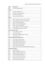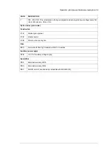
Layout drawings
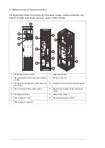
The figure below shows the components of the brake chopper cubicle with bottom entry
and exit of cables and shrouds removed.
Cable entries for brake resistor and control
cables
6
Control panel (J400)
1
Terminals for brake resistor cable connection
7
Drive monitoring display (J401)
2
Brake resistor fuses
8
Brake chopper fuses
3
BCU-x2 control unit
9
Brake chopper module
4
Cabinet heater (G300)
10
Brake chopper cooling fan
5
Operation principle and hardware description 15
Содержание ACS880-607 Series
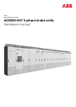
Страница 1: ... ABB INDUSTRIAL DRIVES ACS880 607 3 phase brake units Hardware manual ...
Страница 2: ......
Страница 4: ......
Страница 8: ...8 ...
Страница 12: ...12 ...
Страница 30: ...30 ...
Страница 32: ...32 ...
Страница 36: ...36 ...
Страница 44: ...44 ...
Страница 54: ...54 ...
Страница 62: ...62 ...
Страница 66: ...66 Maintenance ...
Страница 82: ...Dimension drawing bottom exit 82 Dimension drawings ...
Страница 83: ...Dimension drawings 83 ...
Страница 84: ...Dimension drawing top exit 84 Dimension drawings ...
Страница 85: ... Dimension drawings 85 ...
Страница 86: ......

