


37
•
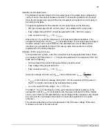
Disable fault function “Cross connection” (par. 30.08), if the
external DC supply
(other than ACS850 drive module) is used
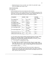
General technical data
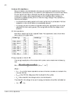
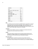
DC voltage limits
All drive modules have their own terminals for the DC connection.
Different limit values in drive modules related to the DC voltage level are defined in the
table below. The values are applicable for firmware versions UIFI2010/UMFI15XX and
above. See the relevant firmware manual for more detailed descriptions.
Designation Symbol
Value Example
(U
DC
= 540 V)
DC voltage range
U
DC
436…743 V
540 V
Charging limit
U
DC,chr
80% U
DC
432
V
DC voltage control:
Overvoltage control limit
U
DC,ovc
125% U
DC
max. 810
675 V
DC voltage control:
Undervoltage control limit
U
DC,uvc
80% U
DC
min. 400
432 V
DC overvoltage trip limit
U
DC,ovt
U
DC,ovc
+ 70 V
max. 880
745 V
DC undervoltage trip limit
U
DC,uvt
U
DC,uvc
– 50 V
min. 350
382 V
Braking chopper limit, low
U
DC,brcl
U
DC,ovc
– 30 V
645 V
Braking chopper limit, high
U
DC,brch
U
DC,ovc
+ 30 V
705 V
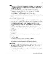
U
DC
in the Value column, where the values are defined, is based on the drive module
setting for the used supply voltage. The used supply voltage can be set with a
parameter (Par. 47.03 and 47.04) or identified automatically. The used
U
DC
value is
then defined according to the following formula:
U
DC
= 1.35
×
(signal: 1.19 USED SUPPLY VOLT)
•
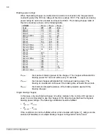
DC voltage range
: the actual DC voltage level with 3-phase AC supply voltage
range (380…480 V AC +10% / -15%). The actual DC voltage with the nominal load
can be defined based on the 3-phase AC supply voltage with the following formula:
The average DC voltage:
ac
ave
dc
U
U
×
≈
35
.
1
,
•
Charging limit
: the charging relay will be closed when the DC voltage level is
reached. There are also other criteria (du/dt, time delay) in firmware for closing the
charging relay. The charging relay is opened if the DC link voltage is below 75 % of
the
U
DC
when the drive is not running.
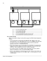
Common DC configurations
Содержание ACS850 series
Страница 1: ...ACS850 Common DC configuration application guide...
Страница 2: ......
Страница 4: ......
Страница 6: ...6 Safety instructions...
Страница 9: ...9 Table of contents...
Страница 11: ...11 Introduction to the manual...
Страница 39: ...EFFECTIVE 22 3 2010 3AUA0000073108 REV A EN...


