


36
1
4
3
6
5
4
3
6
4
3
2
M
M
M
1
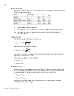
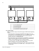
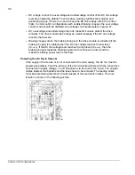
L1, L2, L3, PE (from top to down)
2
U1, V1, W1 (from left to right)
3
U2, V2, W2 (from left to right)
4
DC+, DC- (from left to right)
5
JCU connectors XPOW:2 and XRO:2 (from left to right)
6
JCU connectors XD24:1 and XDI:A (from left to right)
Drive module settings
Note:
The parameter settings mentioned below apply to ACS850 Standard Application
Program.
•
It is recommended to set parameter 99.05 MOTOR CTRL MODE to DTC and to
adjust parameters 20.12 P MOTORING LIM and 20.13 P GENERATING LIM to limit
the maximum power. The calculated braking power can also be used as the
parameter value of 20.13 P GENERATING LIM.
•
When brake chopper is used, set parameter 48.01 BC ENABLE. This activates the
chopper when the DC voltage is high. Also the parameter 47.01 OVERVOLTAGE
CONTROL must be disabled from all of the converters separately.
•
All converters must be in the READY state before starting. See section
READY
signals
for instructions on how to connect the READY signals.
•
Switch on the possible DC contactors based on Table 1 after all of the DC links are
charged and the converters are in the READY state, i.e. when the power is on and
no faults appear.
Common DC configurations
Содержание ACS850 series
Страница 1: ...ACS850 Common DC configuration application guide...
Страница 2: ......
Страница 4: ......
Страница 6: ...6 Safety instructions...
Страница 9: ...9 Table of contents...
Страница 11: ...11 Introduction to the manual...
Страница 39: ...EFFECTIVE 22 3 2010 3AUA0000073108 REV A EN...


