


35
Cables
• Select the input power cables as described in the appropriate drive
Hardware Manual
.
The cross-sectional area of the DC cables must be the same as the
cross-sectional
area of the AC side cables.
• If screened DC cables are used, ground the screen at the other end only.
• The lengths of the supply cables must not differ more than 15%. This applies
especially to converters equipped with DC chokes.
• Maximum length of the DC cables between two converters is 50 m.
• If the system consists of more than two converters, the DC links must be connected in
an external terminal box. Do not use the terminals of one of the converters for this
purpose.
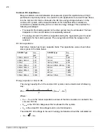
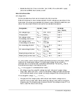
Contactors, DC bus and brake circuit
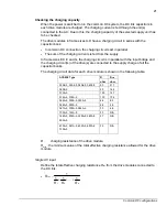
If converters with different charging circuits are connected directly to the main supply,
the DC links must be connected together via contactors. With an external or an internal
brake chopper a contactor must be used for protection against brake chopper faults.
•
Contactors must be capable of cutting off the DC current.
The maximum
operational voltage over the contactor is the DC voltage during the braking, i.e. 1.21
·
1.35
· U
1
.
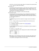
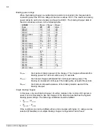
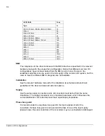
• DC current rating for the DC contactor can be calculated by as follows:
P
cont.max
is the drive power rating of the biggest converter and
U
1
is the supply voltage of
the converter.
I
DC
=
P
DC
/
U
DC
P
DC
≈
P
cont.max
U
DC
= 1.35
U
1
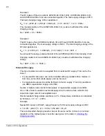
Peak current through the contactor in brake resistor circuit can be calculated as
follows:
I
ˆ=(1.21
U
DC
) /
R
brake
The rms current during the braking can be calculated as follows:
I
rms
=(
P
br
/
R
brake
)
½
R
brake
is the brake resistor‘s resistance.
P
br
is the applied braking power
.
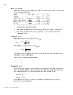
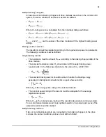
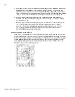
READY signals
To ensure that all of the DC links have been charged before the system is started, the
READY signals of the converters must be wired together. If this is neglected, the
charging resistor can be damaged.
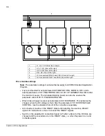
Wire together the READY signals of all the converters connected to the main supply
and the START INTERLOCK signals of all of the converters not connected to the main
supply. An example is presented below.
Common DC configurations
Содержание ACS850 series
Страница 1: ...ACS850 Common DC configuration application guide...
Страница 2: ......
Страница 4: ......
Страница 6: ...6 Safety instructions...
Страница 9: ...9 Table of contents...
Страница 11: ...11 Introduction to the manual...
Страница 39: ...EFFECTIVE 22 3 2010 3AUA0000073108 REV A EN...


