


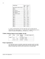


18
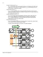
Average motoring power P
mot,ave
P
mot,ave
is the average of the
motoring
DC link power over the whole cycle. This power
is taken from the AC supply. For long load cycles,
P
mot,ave
should be determined over
the worst-case 3 minutes time window.
Peak motoring power P
mot,max
P
mot,max
is the positive peak power in the power profile. This value can have a major
impact on the selection of the drive module(s) connected to the AC supply if many axes
are accelerated simultaneously.
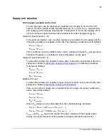
Average regenerative power P
gen,ave
P
gen,ave
is the average of the
regenerating
DC link power over the whole cycle. This
power must be dissipated in the braking resistor(s) or fed back to the AC supply.
P
gen,ave
should be determined over the worst-case 30 seconds time window if the
internal braking chopper of the drive is used.
Peak regenerative power P
gen,max
P
gen,max
is the negative peak power in the power profile. This value has a major impact
on the number of active braking choppers needed.
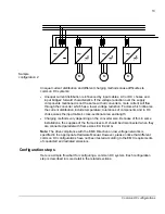
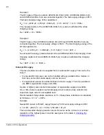
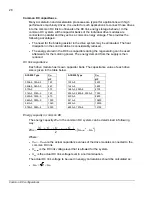
The power values defined above are shown in the following diagram.
~
=
~
=
~
=
~
=
~
=
Pdc
1
M
1
M
2
M
3
M
n
R
2
R
3
Braking
resistor(s)
System po
wer
p
rofile
P
mot,ave
P
mot,max
P
gen,ave
P
gen,max
Pdc
2
Pdc
3
Pdc
n
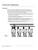
Common DC configurations
Содержание ACS850 series
Страница 1: ...ACS850 Common DC configuration application guide...
Страница 2: ......
Страница 4: ......
Страница 6: ...6 Safety instructions...
Страница 9: ...9 Table of contents...
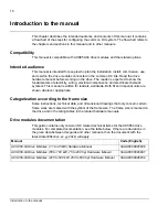
Страница 11: ...11 Introduction to the manual...
Страница 39: ...EFFECTIVE 22 3 2010 3AUA0000073108 REV A EN...


