


30
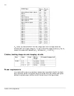
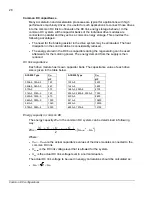
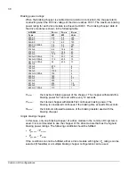
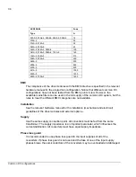
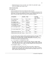
Braking power ratings
When the braking chopper is enabled and a resistor is connected, the chopper starts
conducting when the DC link voltage of the drive reaches 780 V. The maximum braking
power rating for each drive module is achieved at 840 V. The braking chopper data of
the drive modules is shown in the following table.
ACS850 P
br,cont
P
br,max
R
br,min
Type
kW kW ohm
03A0-5
0.9 5.5 120
03A6-5
1.3 5.5 120
04A8-5
1.8 5.5 120
06A0-5,
08A0-5 2.6 5.5 120
010A-5
4.5 7.9 80
014A-5 6.6
14.6
40
018A-5 8.5
14.6
40
025A-5
10.5 30.7 20
030A-5, 035A-5
12
30.7
20
044A-5,
050A-5
17.5 43.9 13
061A-5, 078A-5,
094A-5
36 43.9
13
103A-5 67.5
8
144A-5 75
6
166A-5 112.5
4
202A-5, 225A-5
135
4
260A-5 160
4
290A-5 200
2.7
430A-5 300
2
521A-5 234
1.8
602A-5 210
1.35
693A-5, 720A-5
170
1
P
br,max
:
the maximum braking power of the chopper. The chopper withstands this
braking power for 1 second within every 10 seconds.
P
br,cont
:
the internal chopper withstands this continuous braking power. The
braking is considered continuous if the braking time exceeds 30 seconds.
R
br,min
:
the minimum allowed resistance of the braking resistor used with the
braking chopper.
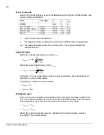
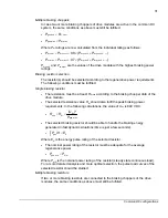
Single braking chopper
In this case, only one braking chopper of a drive module in the common DC system is
used. It is recommended to use the chopper of the drive module that has the highest
braking power ratings. The following conditions should be fulfilled:
•
cont
,
br
ave
,
gen
P
P
<
•
,max
br
,max
gen
P
P
<
If the conditions can not be fulfilled, either a drive module with higher
P
br
ratings can be
selected (if feasible) or a multiple braking chopper configuration can be used.
Common DC configurations
Содержание ACS850 series
Страница 1: ...ACS850 Common DC configuration application guide...
Страница 2: ......
Страница 4: ......
Страница 6: ...6 Safety instructions...
Страница 9: ...9 Table of contents...
Страница 11: ...11 Introduction to the manual...
Страница 39: ...EFFECTIVE 22 3 2010 3AUA0000073108 REV A EN...


