


59
11.
Technical Data
11.1.
Environmental
Ambient temperature range: Operational
: -10 … 50
C (Refer to section 11.5 for Derating Information)
Storage and Transportation : -40
C … 60
C
Max altitude for rated operation
: 1000m (Refer to section 11.5 for derating Information)
Relative Humidity
: < 95% (non condensing)
Note
:
Drive must be Frost and moisture free at all times
Installation above 2000m is not UL approved
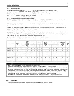
11.2.
Input/Output Current ratings and fuses
The following tables provide the output current rating information for the various ACS255 models. ABB Drives always recommend that selection
of the correct ACS255 is based upon the motor full load current at the incoming supply voltage.
Cable dimensioning for nominal rated currents is shown in the table below together with the corresponding fuse types for short-circuit
protection of the input power cable.
The rated fuse currents given in the table are the maximums for the mentioned fuse types. If smaller fuse ratings are used, check that the fuse
rms current rating is larger than the nominal input current.
If 150% output power is needed, multiply nominal input current by 1.5.
Check that the operating time of the fuse is below 0.5 seconds. The operating time depends on the fuse type, the supply network impedance as
well as the cross-sectional area, material and length of the supply cable. In case the 0.5 seconds operating time is exceeded with the gG or T
fuses, ultra rapid (aR) fuses in most cases reduce the operating time to an acceptable level.
Note:
Larger fuses must not be used when the input power cable is selected according to this table.
Model Number
Power
(HP)
Nominal
Input
Current (A)
Nominal
Input
Current
With 3% line
choke
(A)
Fuse
(A)
Supply and PE
Cable Size
Nominal
Output
Current
(A)
Motor Cable
Size
Maximum
Motor
Cable
Length
Recommended
Brake
Resistance
(Ω)
Frame
Size
gG
UL
Class
CC or J
mm
2
AWG
mm
2
AWG
Mtrs
ACS255-03U-02A1-6..
1
2.7
2.1
10
6
1.5
14
2.1
1.5
14
100
600
P2
ACS255-03U-03A1-6..
2
3.7
3.1
10
6
1.5
14
3.1
1.5
14
100
300
P2
ACS255-03U-04A1-6..
3
4.8
4.1
10
10
1.5
14
4.1
1.5
14
100
200
P2
ACS255-03U-06A5-6..
5
7.1
6.5
10
10
1.5
14
6.5
1.5
14
100
150
P2
ACS255-03U-09A0-6..
7.5
10.2
9.0
16
15
2.5
12
9
1.5
14
100
100
P2
ACS255-03U-12A0-6..
10
14.4
12
25
20
4
10
12
1.5
14
100
80
P3
ACS255-03U-17A0-6..
15
19.1
17
25
25
4
8
17
2.5
10
100
50
P3
ACS255-03U-22A0-6..
20
23.6
22
40
35
10
8
22
4
10
100
33
P3
Note
Input current measurements are at 575VAC at drive nominal output current.
Ratings shown above apply to 40°C Ambient temperature. For derating information, refer to section 11.5.1 on page 60.
The maximum motor cable length stated applies to using a shielded motor cable. When using an unshielded cable, the maximum cable length
limit may be increased by 50%. When using the ABB Drives recommended output choke, the maximum cable length may be increased by 100%
The PWM output switching from any inverter when used with a long motor cable length can cause an increase in the voltage at the motor
terminals, depending on the motor cable length and inductance. The rise time and peak voltage can affect the service life of the motor. ABB
Drives recommend using an output choke for motor cable lengths of 50m or more to ensure good motor service life
For UL compliant installation, use Copper wire with a minimum insulation temperature rating of 70°C, UL Class CC or Class J Fuses
11.3.
Overload
The ACS255 can deliver 150% of the drive nominal output current for 60 seconds and 200 % for 3 seconds.