48
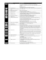
Parameters in the Long parameter mode
Index
Name/Selection
Description
Def
2006
MAINS LOSS RIDE
THROUGH / STOP
CONTROL
Controls the behaviour of the drive in response to a loss of mains power supply whilst the
drive is enabled.
0: Mains
Loss Ride
Through.
0: MAINS LOSS RIDE
THROUGH.
The ACS255 will attempt to continue operating by recovering energy from the load motor.
Providing that the mains loss period is short, and sufficient energy can be recovered before
the drive control electronics power off, the drive will automatically restart on return of mains
power.
1: COAST TO STOP.
The ACS255 will immediately disable the output to the motor, allowing the load to coast or
free wheel. When using this setting with high inertia loads, the Spin Start function Parameter
2101 SPIN START ENABLE may need to be enabled.
2: FAST RAMP TO STOP.
The drive will ramp to stop at the rate programmed in the 2
nd
deceleration time as set in
parameter 2206 2
nd
DECELERATION RAMP TIME.
3: DC BUS POWER SUPPLY
MODE.
This mode is intended to be used when the drive is powered directly via the +DC and –DC Bus
connections. Refer to your ABB Sales Partner for further details.
2007
MINIMUM FREQUENCY /
SPEED LIMIT
Minimum output frequency or motor speed limit – Hz or rpm.
If parameter 9908 MOTOR RATED SPEED >0, the value entered / displayed is in Rpm
0.0 Hz
0.0 HZ…2008
Minimum frequency
2008
MAXIMUM FREQUENCY /
SPEED LIMIT
Maximum output frequency or motor speed limit – Hz or rpm.
If parameter 9908 MOTOR RATED SPEED >0, the value entered / displayed is in Rpm
60.0 Hz
2007…500.0 Hz
Maximum frequency
2014
TORQUE CONTROL
REFERENCE / LIMIT
SOURCE
When parameter 9903 MOTOR CONTROL MODE = 0, this parameter defines the source for
the maximum output torque limit.
When parameter 9903 MOTOR CONTROL MODE = 1, this parameter defines the source for
the torque reference (setpoint).
0: Fixed
Digital
0: FIXED DIGITAL
The torque controller reference / limit is set in parameter 2017 MAXIMUM MOTORING
TORQUE LIMIT/CURRENT LIMIT.
1: ANALOG INPUT 1
The output torque is controlled based on the signal applied to Analog Input 1, whereby 100%
input signal level will result in the drive output torque being limited by the value set in
parameter 2017 MAXIMUM MOTORING TORQUE LIMIT/CURRENT LIMIT.
2: ANALOG INPUT 2
The output torque is controlled based on the signal applied to Analog Input 2, whereby 100%
input signal level will result in the drive output torque being limited by the value set in
parameter 2017 MAXIMUM MOTORING TORQUE LIMIT/CURRENT LIMIT..
3: FIELDBUS.
The output torque is controlled based on the signal from the communications Fieldbus,
whereby 100% input signal level will result in the drive output torque being limited by the
value set in parameter 2017 MAXIMUM MOTORING TORQUE LIMIT/CURRENT LIMIT..
2015
MINIMUM MOTORING
TORQUE LIMIT
Active only in Vector Speed or Vector Torque motor control modes (9903 MOTOR CONTROL
MODE = 0 or 1). Sets a minimum torque limit, whereby when the ACS255 is enabled, it will
always attempt to maintain this torque on the motor at all times whilst operating.
WARNING : This parameter should be used with extreme care, as the drive output frequency
will increase to achieve the torque level, and may exceed the selected speed reference.
0.0%
0.0 %…2017
2017
MAXIMUM MOTORING
TORQUE LIMIT / CURRENT
LIMIT
When operating in Vector Speed or Vector Torque motor control modes (9903 MOTOR
CONTROL MODE = 0 or 1) this parameter defines the maximum torque limit or reference
used by the drive in conjunction with parameter 2014 TORQUE CONTROL REFERENCE/LIMIT
SOURCE .
When operating in V/F Mode (9903 MOTOR CONTROL MODE = 2), this parameter defines the
maximum output current the drive will provide to the motor before reducing the output
frequency to attempt to limit the current.
200.0%
2015…500.00 %
2022
GENERATOR MODE MAX.
TORQUE LIMIT
(MAXIMUM
REGENERATIVE TORQUE)
Active only in Vector Speed or Vector Torque motor control modes (parameter 9903 = 0,1,3).
Sets the maximum regenerating torque allowed by the ACS255
200.0%
0.0…500 %
21 START/STOP
Start and Stop modes of the motor
2101
SPIN START ENABLE
Starting the drive connected to a rotating motor.
0 : Disabled
0 : DISABLED
1 : ENABLED
On start up the drive will attempt to determine if the motor is already rotating, and will
begin to control the motor from its current speed. A short delay may be observed when
starting motors which are not turning.


