46
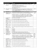
Parameters in the Long parameter mode
Index
Name/Selection
Description
Def
9 : RESERVED.
No Function
10 : RESERVED
No Function
11 : RESERVED.
No Function
12 : DRIVE TRIPPED
Logic 1 when the drive has tripped and the display shows the fault code.
13 : STO STATUS
Logic 1 when both STO inputs are present and the drive is able to be operated
1404
RELAY OUTPUT
HYSTERESIS CONTROL
This parameter works in conjunction with parameter 1501 ANALOG OUTPUT 1 FUNCTION
SELECT and 1507 ANALOG OUTPUT 2 FUNCTION SELECT = 2 or 3 to set a band around the
target speed (1501 = 2) or zero speed (1501 = 3). When the speed is within this band, the
drive is considered to be at target speed or Zero speed.
This function is used to prevent “chatter” on the relay output if the operating speed
coincides with the level at which the digital / relay output changes state. e.g. if parameter
1507 ANALOG OUTPUT 2 FUNCTION SELECT = 3, 2008 MAXIMUM FREQUENCY/SPEED LIMIT =
50Hz and parameter 1404 = 5%, the relay contacts close above 2.5Hz
0.3%
0.0…25%
15
ANALOG/DIGITAL
OUTPUTS
Analog output signal processing
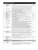
1501
ANALOG OUTPUT 1
(TERMINAL 8) FUNCTION
SELECT
Selects the type of output signal information indicated from terminal 8.
Note :
When using settings 0 – 7 the output is a digital format (Logic 1 = 24V).
When using settings 8– 11 the output is an analog format.
Note : When using settings 4 – 7, parameters 3203 ADJUSTABLE THRESHOLD 1 UPPER LIMIT
and 3202 ADJUSTABLE THRESHOLD 1 LOWER LIMIT must be used together to control the
behaviour. The output will switch to Logic 1 when the selected signal exceeds the value
programmed in parameters 3203 ADJUSTABLE THRESHOLD 1 UPPER LIMIT, and return to
Logic 0 when the signal falls below the value programmed in 3202 ADJUSTABLE THRESHOLD
1 LOWER LIMIT.
8 : Output
Frequency
(Motor
Speed)
0 : DRIVE ENABLED
(RUNNING)
Logic 1 when the ACS255 is enabled (Running)
1: DRIVE READY
Logic 1 When no Fault condition exists on the drive
2 : AT TARGET FREQUENCY
(SPEED).
Logic 1 when the output frequency matches the setpoint frequency
3 : OUTPUT FREQUENCY
> 0.0
Logic 1 when the motor runs above zero speed
4 : OUTPUT FREQUENCY
>= LIMIT
Logic 1 when the motor speed exceeds the adjustable limit. (See note above)
5 : OUTPUT CURRENT >=
LIMIT
Logic 1 when the motor current exceeds the adjustable limit. (See note above)
6 : MOTOR TORQUE >=
LIMIT
Logic 1 when the motor torque exceeds the adjustable limit. (See note above)
7 : ANALOG INPUT 2
SIGNAL LEVEL >= LIMIT.
Logic 1 when the signal applied to the Analog Input 2 exceeds the adjustable limit. (See note
above)
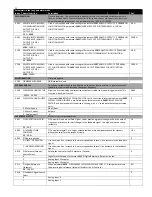
8 : OUTPUT FREQUENCY
(MOTOR SPEED).
0 to Parameter 2008 MAXIMUM FREQUENCY/SPEED LIMIT
9 : OUTPUT (MOTOR)
CURRENT.
0 to 200% of Parameter 9906 MOTOR RATED CURRENT
10 : MOTOR TORQUE.
0 to 200% of motor rated torque
11 : OUTPUT (MOTOR)
POWER
0 to 150% of drive rated power
1504
ANALOG OUTPUT 1
(TERMINAL 8) FORMAT
Selects the type of output signal from terminal 8
0 to 10V
10 to 0V
0 to 20mA
20 to 0mA
4 to 20mA
20 to 4mA


