background image


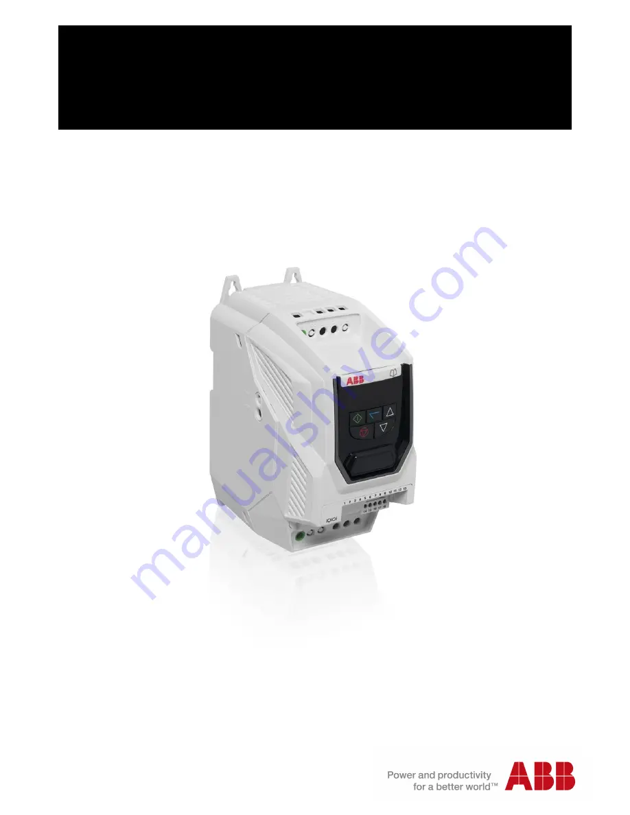
ABB Micro drives


User’s manual 

ACS255 

drives (0.5…20 hp) (600V Variants) 


Содержание ACS255

Страница 1: ...ABB Micro drives User s manual ACS255 drives 0 5 20 hp 600V Variants ...

Страница 2: ...List of related manuals Option manuals and guides Code English ACS255 user s manual for 115 480V variants 3AXD10000528266 ...

Страница 3: ...3 ACS255 drives 0 5 20 hp User s manual 3AXD10000528265 Rev A EN EFFECTIVE 2016 09 13 2016 ABB Oy All Rights Reserved ...

Страница 4: ..._________ 17 4 6 Mounting the Drive IP20 Units __________________________________________________________ 17 4 7 Guidelines for mounting IP66 Units _______________________________________________________ 18 4 8 Removing the Terminal Cover ____________________________________________________________ 18 4 9 Routine Maintenance ___________________________________________________________________ 18 5 ...

Страница 5: ...____ 39 9 3 Read Only Status parameters_____________________________________________________________ 41 9 4 Parameters in the Long parameter mode ___________________________________________________ 43 9 5 Preventing un authorized parameter editing ________________________________________________ 54 10 Serial communications ______________________________________________________________ 55 10 1 RJ45...

Страница 6: ...ry default parameter settings Run Stop 10K Speed Pot Close the switch to run enable open to stop Motor Cable o Cable size recommendation values given on page 59 o Observe the maximum permissible motor cable length o For Motor cable lengths 50 metres an output filter is recommended o Use a screened shielded cable Motor Connection Check for Star or Delta Connection according to the motor voltage rat...

Страница 7: ...Observe the maximum permissible motor cable length For Motor cable lengths 50 metres an output filter is recommended Use a screened shielded cable The shield should be bonded to earth at both ends Motor Connection Check for Star or Delta Connection according to the motor voltage rating See page 22 Enter the Motor Nameplate Data into the drive Parameters as follows Motor Rated Voltage 9905 Motor Ra...

Страница 8: ...ironment in which the drive is installed motor switching frequency motor cable lengths and installation methods adopted For motor cable lengths greater than 100m an output dv dt filter must be used please refer to the please refer to the http www abb com ProductGuide for further details Vector Speed and Torque control modes may not operate correctly with long motor cables and output filters It is ...

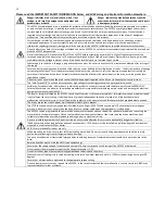
Страница 9: ...wer is applied After disconnecting the input power always wait for 10 minutes to let the intermediate circuit capacitors discharge before you start working on the drive motor or motor cable Always ensure by measuring with a multimeter impedance at least 1 Mohm that 1 There is no voltage between the drive input phases L1 L2 and L3 and the ground 2 There is no voltage between terminals and BR and th...

Страница 10: ...putting it into service make sure that the motor and all driven equipment are suitable for operation throughout the speed range provided by the drive The drive can be adjusted to operate the motor at speeds above and below the speed provided by connecting the motor directly to the power line Do not activate automatic fault reset functions if dangerous situations can occur When activated these func...

Страница 11: ...rque Off Function does not prevent high voltages from being present at the drives power terminals Within the European Union all machinery in which this product is used must comply with the Machinery Directive 2006 42 EC Safety of Machinery In particular the machine manufacturer is responsible for providing a main switch and ensuring the electrical equipment complies with EN60204 1 The level of int...

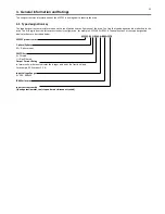
Страница 12: ...the left express the basic configuration for example ACS255 03U 02A1 6 The explanations of the type designation label selections are described below ACS255 03 U 02A1 6 B063 F278 ACS255 product series 1 phase 3 phase 03 3 phase input EMC Filter E Filtered U Non Filtered Output Current Rating In format xxAy where xx indicates the integer part and y the fractional part For example 02A1 means 2 1 A In...

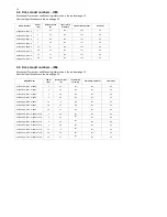
Страница 13: ...Mounting information is shown from page 15 Electrical Specifications are shown on page 59 Model Number Power HP Output Current A Input switch assembly Internal DB transistor Frame Size ACS255 03U 02A1 6 B063 1 2 1 No Yes P2 ACS255 03U 03A1 6 B063 2 3 1 No Yes P2 ACS255 03U 04A1 6 B063 3 4 1 No Yes P2 ACS255 03U 06A5 6 B063 5 6 5 No Yes P2 ACS255 03U 09A0 6 B063 7 5 9 No Yes P2 ACS255 03U 12A0 6 B0...

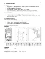
Страница 14: ...e ACS255 in its original box until required Storage should be clean and dry and within the temperature range 40 C to 60 C 4 3 UL Compliant Installation Note the following for UL compliant installation For an up to date list of UL compliant products please refer to UL listing NMMS E211945 The drive can be operated within an ambient temperature range as stated in section 11 1 For IP20 units installa...

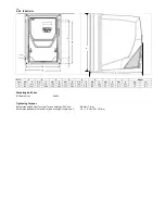
Страница 15: ... 41 188 7 40 176 6 93 4 2 0 17 8 5 0 33 4 8 10 6 3 310 12 20 277 10 89 252 9 90 251 9 88 211 8 29 198 7 78 4 2 0 17 8 5 0 33 7 3 16 1 Mounting Bolt Sizes All Frame Sizes 4 x M4 Tightening Torques Recommended Control Terminal Torque Settings All Sizes 0 8 Nm 7 lb in Recommended Power Terminal Torque Settings Frame Size 2 1 2 1 5 Nm 10 15 lb in A ...

Страница 16: ...unted in non ventilated metallic enclosures Drive Frame Size X Above Below Y Either Side Z Between mm in mm in mm in 2 75 2 95 50 1 97 46 1 81 3 100 3 94 50 1 97 52 2 05 Note Dimension Z assumes that the drives are mounted side by side with no clearance Typical drive heat losses are 3 of operating load conditions Above are guidelines only and the operating ambient temperature of the drive MUST be ...

Страница 17: ...ve mark the locations required for drilling Suitable cable glands to maintain the ingress protection of the drive are required Gland holes for power and motor cables are pre moulded into the drive enclosure recommended gland sizes are shown above gland holes for control cables may be cut as required 4 8 Removing the Terminal Cover Frame Sizes 2 3 Using a suitable flat blade screwdriver rotate the ...

Страница 18: ...iliar with the construction and operation of this equipment and the hazards involved should install adjust operate or service this equipment Read and understand this manual and other applicable manuals in their entirety before proceeding Failure to observe this precaution could result in severe bodily injury or loss of life 5 1 1 Recommended installation for EMC compliance Whenever possible use Sh...

Страница 19: ... the voltage at which it will be operated For more information refer to section 5 6 Motor Terminal Box Connections Type MC continuous corrugated aluminium armour cable with symmetrical grounds or shielded power cable is recommended for the motor cables if metallic conduit is not used The power cables must be rated for 75 C 167 F 5 3 Incoming Power Connection Power should be connected to L1 L2 and ...

Страница 20: ...on an IT system an ungrounded power system or high resistance grounded power system otherwise the system will be connected to ground potential through the EMC capacitors This may cause danger or damage to the EMC filter If you have an IT ungrounded system or corner grounded TN system disconnect the internal Varistor screw as shown below ...

Страница 21: ...sure the cable screen may be terminated directly to the control panel using a suitable EMC clamp or gland as close to the drive as possible For IP66 drives connect the motor cable screen to the internal ground clamp 5 6 Motor Terminal Box Connections Most general purpose motors are wound for operation on dual voltage supplies This is indicated on the nameplate of the motor This operational voltage...

Страница 22: ...e Rotation DI2 3 Digital Input 3 Analog Speed Ref Preset Speed DI3 4 Digital Inputs 8 30 Volt DC 10 Volt 10mA Output 10V 5 Analog Input 1 DI AI4 6 0V 7 0V Output Speed Analog Output 0 10 Volt 4 20mA 20mA Max 8 AO1 0 Volt Supply External Input 0V 9 0V Output Current Analog Input 2 DI AI5 10 Analog Output 0 10 Volt 4 20mA 20mA Max 11 AO2 SAFE TORQUE OFF Input Also refer to page 24 for further inform...

Страница 23: ...stop in accordance with category 0 Emergency Off of IEC 60204 1 This means that the motor will coast to a stop when the STO function is activated this method of stopping should be confirmed as being acceptable to the system the motor is driving The STO function is recognised as a fail safe method even in the case where the STO signal is absent and a single fault within the drive has occured the dr...

Страница 24: ...etting parameter 1401 USER RELAY 1 OUTPUT TERMINALS 14 15 16 FUNCTION SELECT to a value of 13 will result in relay opening when the STO function is activated Drive relay 2 Setting parameter 1402 USER RELAY 2 OUTPUT TERMINALS 17 18 FUNCTION SELECT to a value of 13 will result in relay opening when the STO function is activated STO Fault Codes Fault Code Code Number Description Corrective Action Sto...

Страница 25: ... circuit to an external Voltage source External Power Supply Protected shielded cables 1213 Protective Capped Trunking or equivalent to prevent STO Cable short circuit to an external Voltage source 1 7 Safety relay Note The Maximum cable length from Voltage source to the drive terminals should not exceed 25 metres 5 10 7 2 External Power supply Specification Voltage Rating Nominal 24Vdc STO Logic ...

Страница 26: ...TION SELECT and check that the drive still displays Inhibit and that the operation is in line with the section 5 10 4 STO Operation and section 5 10 5 STO Status and Monitoring With the motor running normally from the drive o De energise the STO inputs o Check that the drive displays InHibit and that the motor stops and that the operation is in line with the section 5 10 4 STO Operation and sectio...

Страница 27: ...tween status and parameter mode UP Used to increase speed in real time mode or to increase parameter values in parameter edit mode DOWN Used to decrease speed in real time mode or to decrease parameter values in parameter edit mode RESET STOP Used to reset a tripped drive When in Keypad mode is used to Stop a running drive START When in keypad mode used to Start a stopped drive or to reverse the d...

Страница 28: ...29 6 3 Resetting Parameters to Factory Default Settings ...

Страница 29: ...ve mains power applied but no Enable or Run signal applied Motor Autotune in progress x x Drive running display shows output frequency Hz Whilst the drive is running the following displays can be selected by briefly pressing the button on the drive Each press of the button will cycle the display through to the next selection x x Drive running display shows motor current Amps x x Drive Running disp...

Страница 30: ...Amps briefly press the Navigate key Press again to display the motor power Press again to display the estimated motor speed RPM Motor nameplate RPM must be entered in 9908 motor rated speed Press again to return to speed Hz display To stop the motor disable the drive by opening the control switch terminals 1 2 If the enable disable switch is opened the drive will decelerate to stop at which time t...

Страница 31: ...n most applications the default Voltage Vector control mode will provide adequate performance however if Sensorless Vector operation is required use the following procedure Enter the motor nameplate details into the relevant parameters as follows o 9905 MOTOR RATED VOLTAGE o 9906 MOTOR RATED CURRENT o 9907 MOTOR RATED FREQUENCY o Optional 9908 MOTOR RATED SPEED Rpm o 9915 Motor Power Factor Cos Ø ...

Страница 32: ...Fwd O Stop C Run Rev Digital input 3 Analog input 1 Preset Speed O Decel ramp 1 Par 2203 C Decel ramp 2 Par 2206 1 Off Off Preset Speed 1 On Off Preset Speed 2 Off On Preset Speed 3 On On Preset Speed 4 9902 Digital Input 1 Terminal 2 Digital Input 2 Terminal 3 Digital Input 3 Terminal 4 Analog Input 1 Terminal 6 Analog Input 2 Terminal 10 1 O Stop C Run O Forward C Reverse O Selected Speed Ref C ...

Страница 33: ...Rotation 4 Selected Speed ref Preset Speed ref 4 T4 T6 T10 Preset 5 10 Volt 5 6 Analog Input 1 6 Open Open Open 1202 7 0 Volts 7 Closed Open Open 1203 8 8 Open Closed Open 1204 9 0 Volts 9 Closed Closed Open 1205 10 Preset Speed 1 1202 Preset Speed 2 1203 1203 10 or ma l Op er ati on 11 11 12 Safe Inhibit Normal Operation 12 Safe Inhibit Normal Operation 13 Safe Inhibit Normal Operation 13 Safe In...

Страница 34: ...Closed Closed 1205 4 T4 T6 Preset Open Open 1202 Closed Open 1203 Open Closed 1204 Closed Closed 1205 5 5 6 6 7 7 8 8 9 0 Volts 9 0 Volts 10 External Trip F0014 10 or ma l Op er ati on Decel ramp 1 2203 Decel ramp 2 2206 11 11 12 Safe Inhibit Normal Operation 12 Safe Inhibit Normal Operation 13 Safe Inhibit Normal Operation 13 Safe Inhibit Normal Operation 9902 9 Open Closed 9902 10 Open Closed 1 ...

Страница 35: ...peed ref Preset Speed 1 1202 4 Selected Speed ref Preset Speed 1 1202 5 10 Volt 5 10 Volt 6 Analog Input 1 6 Analog Input 1 7 0 Volts 7 0 Volts 8 8 9 0 Volts 9 10 Analog input 2 E g Torque Reference 10 or m al O pe ra ti on Decel ramp 1 2203 Decel ramp 2 2206 11 11 12 Safe Inhibit Normal Operation 12 Safe Inhibit Normal Operation 13 Safe Inhibit Normal Operation 13 Safe Inhibit Normal Operation 99...

Страница 36: ...on 2 Stop Run Forward 2 Stop Run Forward 3 Stop Run Reverse 3 Stop Run Reverse 4 T4 T6 Preset Open Open 1202 Closed Open 1203 Open Closed 1204 Closed Closed 1205 4 Increase Speed1 5 5 6 6 Decrease Speed1 7 7 8 8 9 0 Volts 9 0 Volts 10 Selected Speed ref Preset Speeds 10 or ma l Op er ati on Selected Speed ref Preset Speed 1 1202 11 11 12 Safe Inhibit Normal Operation 12 Safe Inhibit Normal Operati...

Страница 37: ...PH Press for 1sec to enter Short Long Parameter group selection mode Timeout 300s Use to select Short or Long group parameters PAr SH Press to exit Short Long Parameter group selection mode and save selection Parameter mode End number flashing P9902H PAr SH PAr LH 9 1 2 Parameter Structure table PAr SH Parameter No 9902 9905 9906 9907 0401 1103 1202 1203 1204 1301 2008 2102 2202 ABB Short paramete...

Страница 38: ... section 13 1 for further information 11 REFERENCE SELECT The drive can accept a variety of references in addition to the conventional analog input potentiometer and keypad signals 1103 PRIMARY COMMAND SOURCE MODE 0 Terminal Control 0 TERMINAL CONTROL The drive responds directly to signals applied to the control terminals 1 UNI DIRECTIONAL KEYPAD CONTROL The drive can be controlled in the forward ...

Страница 39: ... can continue to rotate due to inertia and the drive may possibly be re enabled whilst the motor is still rotating the spin start function Parameter 2101 SPIN START ENABLE should be enabled In this mode the drive brake transistor is disabled 2 Ramp To Stop When the enable signal is removed the drive will ramp to stop with the rate controlled by Parameter 2203 DECEL RAMP TIME as described above The...

Страница 40: ...s reset back to 0 0 and the value of Parameter 0141 MWh meter is increased 0120 ANALOG INPUT 1 APPLIED SIGNAL LEVEL Displays the signal level applied to analog input 1 Terminal 6 in after scaling and offsets have been applied 0121 ANALOG INPUT 2 APPLIED SIGNAL LEVEL Displays the signal level applied to analog input 2 Terminal 10 in after scaling and offsets have been applied 0126 PI CONTROLLER OUT...

Страница 41: ...ory read only 0402 DRIVE RUN TIME SINCE LAST TRIP 1 Displays the total operating time of the drive since the last fault occurred The first value shown is the number of hours Pressing the Up key will display the minutes and seconds HH MM SS 0415 DRIVE RUN TIME SINCE LAST TRIP 2 Displays the total operating time of the drive since the last fault occurred The first value shown is the number of hours ...

Страница 42: ...o control or Local Remote control when switched to keypad mode by a digital input the drive will continue to operate at the last operating speed 3 PRESET SPEED 4 Following a stop and restart the ACS255 will always initially run at Preset Speed 4 Par 1205 4 MINIMUM SPEED TERMINAL ENABLE Following a stop and restart the drive will always initially run at the minimum speed parameter 2007 MIN SPEED LI...

Страница 43: ...0 Volt Signal Uni polar 10 to 10 Volt Signal Bi polar 0 to 20mA Signal 4 to 20mA Signal the ACS255 will trip and show the fault code if the signal level falls below 3mA 4 to 20mA Signal the ACS255 will ramp to stop if the signal level falls below 3 mA 20 to 4mA Signal the ACS255 will trip and show the fault code if the signal level falls below 3mA 20 to 4mA Signal the ACS255 will ramp to stop if t...

Страница 44: ... motor is exceeds 0 0Hz 4 OUTPUT FREQUENCY LIMIT Logic 1 when the motor speed exceeds the adjustable limit See note above 5 OUTPUT CURRENT LIMIT Logic 1 when the motor current exceeds the adjustable limit See note above 6 OUTPUT TORQUE LIMIT Logic 1 when the motor torque exceeds the adjustable limit See note above 7 ANALOG INPUT 2 SIGNAL LEVEL LIMIT Logic 1 when the signal applied to the Analog In...

Страница 45: ...3203 ADJUSTABLE THRESHOLD 1 UPPER LIMIT and 3202 ADJUSTABLE THRESHOLD 1 LOWER LIMIT must be used together to control the behaviour The output will switch to Logic 1 when the selected signal exceeds the value programmed in parameters 3203 ADJUSTABLE THRESHOLD 1 UPPER LIMIT and return to Logic 0 when the signal falls below the value programmed in 3202 ADJUSTABLE THRESHOLD 1 LOWER LIMIT 8 Output Freq...

Страница 46: ...put 2 exceeds the adjustable limit See note above 8 OUTPUT FREQUENCY MOTOR SPEED 0 to Parameter 2008 MAXIMUM FREQUENCY SPEED LIMIT 9 OUTPUT MOTOR CURRENT 0 to 200 of Parameter 9906 MOTOR RATED CURRENT 10 MOTOR TORQUE 0 to 200 of motor rated torque 11 OUTPUT MOTOR POWER 0 to 150 of drive rated power 1508 ANALOG OUTPUT 2 TERMINAL 11 FORMAT Selects the type of output signal from terminal 11 0 to 10V ...

Страница 47: ... 100 input signal level will result in the drive output torque being limited by the value set in parameter 2017 MAXIMUM MOTORING TORQUE LIMIT CURRENT LIMIT 2 ANALOG INPUT 2 The output torque is controlled based on the signal applied to Analog Input 2 whereby 100 input signal level will result in the drive output torque being limited by the value set in parameter 2017 MAXIMUM MOTORING TORQUE LIMIT ...

Страница 48: ...START Defines the behaviour of the drive relating to the enable digital input and also configures the Automatic Restart function Following Power on or reset the drive will not start if Digital Input 1 remains closed The Input must be closed after a power on or reset to start the drive Following a Power On or Reset the drive will automatically start if Digital Input 1 is closed to Following a trip ...

Страница 49: ... require the gain to be reduced 50 0 0 1 400 0 2302 VECTOR SPEED CONTROLLER INTEGRAL TIME CONSTANT Sets the integral time for the speed controller Smaller values provide a faster response in reaction to motor load changes at the risk of introducing instability For best dynamic performance the value should be adjusted to suit the connected load 0 050 s 0 000 2 000 s 2303 VECTOR SPEED CONTROL D GAIN...

Страница 50: ...ce the output switching frequency to this value at higher heat sink temperature to reduce the risk of an over temperature trip 4kHz 4 32kHz 2610 V F CHARACTERISTIC ADJUSTMENT VOLTAGE Used in conjunction with parameter 2611 0 0 100 of 9905 2611 V F CHARACTERISTIC ADJUSTMENT FREQUENCY When operating in V F mode Parameter 9903 2 this parameter in conjunction with parameter 2610 sets a frequency point...

Страница 51: ...on the output frequency 3400 DISPLAY SCALING FACTOR Allow the user to display an alternative output unit scaled from an existing parameter This function is disabled if set to 0 0 000 30 000 30 000 3405 DISPLAY SCALING SOURCE If parameter 3400 DISPLAY SCALING FACTOR set 0 the variable selected in parameter 3405 DISPLAY SCALING SOURCE is multiplied by the factor entered in 3400 DISPLAY SCALING FACTO...

Страница 52: ...the motor Volts Drive Rating Dependent 0 660V Voltage Note The stress on the motor insulation is always dependant on the drive supply voltage This also applies in the case where the motor voltage rating is lower than the rating of the drive and the supply of the drive 9906 MOTOR RATED CURRENT This parameter should be set to the rated nameplate current of the motor Drive Rating Dependent 0 2 drive ...

Страница 53: ...ER ADAPTATION ENABLE Allows the stator inductance parameter 11203 MOTOR STATOR INDUCTANCE to be adapted during normal operation 0 DISABLE 1 ENABLE 11209 PULSE WIDTH MINIMUM LIMIT This parameter is used to limit the minimum output pulse width which can be used for long cable applications Increasing the value of this parameter will reduce the risk of over current trips on long motor cables but will ...

Страница 54: ... supports Master Slave Modbus RTU communications using the 03 Read Holding Registers and 06 Write Single Holding Register commands Many Master devices treat the first Register address as Register 0 therefore it may be necessary to convert the Register Numbers detailed in section 10 2 4 by subtracting 1 to obtain the correct Register address The telegram structure is as follows Command 03 Read Hold...

Страница 55: ... to 60000 0 00s to 600 00s 6 Error code Drive status R This register contains 2 bytes The Lower Byte contains an 8 bit drive status word as follows Bit 0 0 Drive Disabled Stopped 1 Drive Enabled Running Bit 1 0 Drive Healthy 1 Drive Tripped The Upper Byte will contain the relevant fault number in the event of a drive trip Refer to section 13 1 on page 62 for a list of fault codes and diagnostic in...

Страница 56: ...IOD 162 2106 DC INJECTION BRAKING VOLTAGE 163 2108 START MODE SELECT AUTOMATIC RESTART 164 2110 LOW FREQUENCY TORQUE BOOST 165 2111 TORQUE BOOST FREQUENCY LIMIT 166 2112 ZERO SPEED HOLDING TIME 167 2202 ACCELERATION RAMP TIME 168 2203 DECELERATION RAMP TIME 169 2206 2ND DECELERATION RAMP TIME FAST STOP 170 2210 FIELDBUS RAMP CONTROL 171 2301 VECTOR SPEED CONTROLLER PROPORTIONAL GAIN 172 2302 VECTO...

Страница 57: ...PUTS FUNCTION SELECT 206 9903 MOTOR CONTROL MODE 207 9905 MOTOR RATED VOLTAGE 208 9906 MOTOR RATED CURRENT 209 9907 MOTOR RATED FREQUENCY 210 9908 MOTOR RATED SPEED 211 9910 MOOTR PARAMETER AUTO TUNE ENABLE 212 11201 MOTOR STATOR RESISTANCE 213 11202 MOTOR ROTOR RESISTANCE 214 11203 MOTOR STATOR INDUCTANCE 215 11204 MOTOR MAGNETISING CURRENT 216 11205 MOTOR LEAKAGE COEFFICIENT 217 11207 QUICK RS M...

Страница 58: ...Input Current A Nominal Input Current With 3 line choke A Fuse A Supply and PE Cable Size Nominal Output Current A Motor Cable Size Maximum Motor Cable Length Recommended Brake Resistance Ω Frame Size gG UL Class CC or J mm2 AWG mm2 AWG Mtrs ACS255 03U 02A1 6 1 2 7 2 1 10 6 1 5 14 2 1 1 5 14 100 600 P2 ACS255 03U 03A1 6 2 3 7 3 1 10 6 1 5 14 3 1 1 5 14 100 300 P2 ACS255 03U 04A1 6 3 4 8 4 1 10 10 ...

Страница 59: ...ed and connected to the drive connection must be carried out according to the information shown in section 5 7 2 11 5 Derating Information Derating of the drive maximum continuous output current capacity is required when Operating at ambient temperature in excess of 40 C 104 F Operating at Altitude in excess of 1000m 3281 ft Operation with Effective Switching Frequency higher than the minimum sett...

Страница 60: ...s optimum motor control Set Motor boost values Set 2110 to 25 Boost Current Level Set 2111 to 10 Boost Frequency 12 1 2 PMSM Motor Auto tune A Motor Auto tune must be carried out in order to measure the motor electrical characteristics during the Auto tune test brakes will be applied by the drive unless controlled by other means Action Additional Information Close Safe Torque off input connections...

Страница 61: ...en successfully completed for the connected motor Check the load mechanically to ensure it is free and that no jams blockages or other mechanical faults exist 05 Hardware Over Current Check the wiring to motor and the motor for phase to phase and phase to earth short circuits Disconnect the motor and motor cable and retest If the drive trips with no motor connected it must be replaced and the syst...

Страница 62: ...ing in parameter 2606 Reduce the load on the motor drive 24 Maximum Torque Limit Exceeded The output torque limit has exceeded the drive capacity or trip threshold Reduce the motor load or increase the acceleration time 26 Drive output fault Drive output fault 29 Internal STO circuit Error Refer to your ABB Sales Partner 40 Autotune Failed Measured motor stator resistance varies between phases Ens...

Отзывы: