


76
ACS 400 User’s Manual
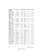
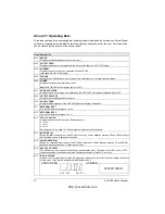
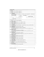
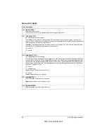
Group 10: Command Inputs
Start, Stop and Direction commands can be given from the control panel or from two external
locations (
EXT
1,
EXT
2). The selection between the two external locations is made with parameter
1102
EXT
1/
EXT
2
SEL
. For more information on control locations refer to “Appendix A” on page 151.
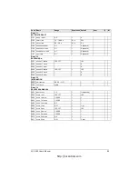
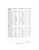
Code Description
1001
EXT1 COMMANDS
Defines the connections and the source of Start/Stop/Direction commands for External control location 1
(
EXT
1).
0
=
NOT
SEL
No Start/Stop/Direction command source for
EXT
1 is selected.
1 = DI1
Two-wire Start/Stop connected to digital input DI1. DI1 deactivated = Stop;
DI1 activated = Start. *
2 = DI1,2
Two-wire Start/Stop, Direction. Start/Stop is connected to digital input DI1 as above. Direction is connected
to digital input DI2. DI2 deactivated = Forward; DI2 activated = Reverse. To control direction, the value of
parameter 1003
DIRECTION
should be
REQUEST
.
3 = DI1P,2P
Three-wire Start/Stop. Start/Stop commands are given by means of momentary push-buttons (the P stands
for “pulse”). The Start push-button is normally open, and connected to digital input DI1. The Stop push-
button is normally closed, and connected to digital input DI2. Multiple Start push-buttons are connected in
parallel; multiple Stop push-buttons are connected in series. *,**
4 = DI1P,2P,3
Three-wire Start/Stop, Direction. Start/Stop connected as with DI1P,2P. Direction is connected to digital
input DI3. DI3 deactivated = Forward; DI3 activated = Reverse. To control Direction, the value of parameter
1003 D
IRECTION
should be
REQUEST
. **
5 = DI1P,2P,3P
Start Forward, Start Reverse, and Stop. Start and Direction commands are given simultaneously with two
separate momentary push-buttons (the P stands for “pulse”). The Stop push-button is normally closed, and
connected to digital input DI3. The Start Forward and Start Reverse push-buttons are normally open, and
connected to digital inputs DI1 and DI2 respectively. Multiple Start push-buttons are connected in parallel,
and multiple Stop push-buttons are connected in series. To control direction, value of parameter 1003
DIRECTION
should be
REQUEST
. **
6 = DI5
Two-wire Start/Stop, connected to digital input DI5. DI5 deactivated = Stop and DI5 activated = Start. *
7 = DI5,4
Two-wire Start/Stop/Direction. Start/Stop is connected to digital input DI5. Direction is connected to digital
input DI4. DI4 deactivated = Forward and DI4 activated = Reverse. To control direction, the value of
parameter 1003
DIRECTION
should be
REQUEST
.
8 =
KEYPAD
The Start/Stop and Direction commands are given from the control panel when External control location 1
is active. To control direction, the value of parameter 1003
DIRECTION
should be
REQUEST
.
9 =
DI
1
F
,2
R
Start forward command is given when DI1= activated and DI2= deactivated. Start reverse command is
given if DI1 is deactivated and DI2 is activated. In other cases Stop command is given.
10 =
COMM
The Start/Stop and Direction commands are given through serial communication.
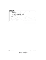
*Note! In cases 1, 3, 6 direction is set with parameter 1003
DIRECTION
. Selecting value 3 (
REQUEST
) fixes
the direction to Forward.
**Note! The stop signal must be activated before a Start command can be given.
http://nicontrols.com
Содержание ACS 400
Страница 3: ...http nicontrols com ...
Страница 5: ...http nicontrols com ...
Страница 7: ...iv ACS 400 User s Manual http nicontrols com ...
Страница 45: ...34 ACS 400 User s Manual http nicontrols com ...
Страница 52: ...ACS 400 User s Manual 41 Motor Will Not Run http nicontrols com ...
Страница 53: ...42 ACS 400 User s Manual Motor Stalls during Acceleration http nicontrols com ...
Страница 54: ...ACS 400 User s Manual 43 Overvoltage Fault Indication http nicontrols com ...
Страница 55: ...44 ACS 400 User s Manual Overcurrent Fault Indication http nicontrols com ...
Страница 56: ...ACS 400 User s Manual 45 Overload Fault Indication http nicontrols com ...
Страница 57: ...46 ACS 400 User s Manual Undervoltage Fault Indication http nicontrols com ...
Страница 58: ...ACS 400 User s Manual 47 External Fault Indication http nicontrols com ...
Страница 59: ...48 ACS 400 User s Manual No Operator Display http nicontrols com ...
Страница 75: ...64 ACS 400 User s Manual http nicontrols com ...
Страница 161: ...150 ACS 400 User s Manual http nicontrols com ...
Страница 167: ...156 ACS 400 User s Manual http nicontrols com ...
Страница 177: ...166 ACS 400 User s Manual http nicontrols com ...
Страница 179: ...168 ACS 400 User s Manual ACS 400 NEMA Type 1 Enclosure R2 Frame Size http nicontrols com ...
Страница 180: ...ACS 400 User s Manual 169 ACS 400 NEMA Type 1 Enclosure R3 Frame Size http nicontrols com ...
Страница 181: ...170 ACS 400 User s Manual ACS 400 NEMA Type 1 Enclosure R4 Frame Size http nicontrols com ...
Страница 182: ...ACS 400 User s Manual 171 ACS 400 NEMA Type 12 4 Enclosure R1 Frame Size http nicontrols com ...
Страница 183: ...172 ACS 400 User s Manual ACS 400 NEMA 12 4 Enclosure R2 Frame Size http nicontrols com ...
Страница 184: ...ACS 400 User s Manual 173 ACS 400 NEMA Type 12 4 R3 Frame Size http nicontrols com ...
Страница 185: ...174 ACS 400 User s Manual ACS 400 NEMA Type 12 4 R4 Frame Size http nicontrols com ...
Страница 186: ...http nicontrols com ...