


ACS 400 User’s Manual
121
8117
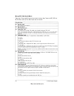
NR OF AUX MOT
Sets the number of auxiliary motors.
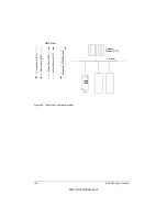
Relay outputs
Start/stop signals for the auxiliary motors are given through relay outputs. In addition, one relay output is
used to connect the speed regulated motor to the ACS 400.
ACS 400 relay outputs RO1 and RO2 can be used to control the motors. It is also possible to use up to two
optional external digital input/output modules (NDIO).
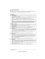
ACS 400 relay output 1 is used for Pump and Fan motor control if the value of 1401 RELAY OUTPUT 1 is
29 (PFC). Relay output 2 is used for Pump and Fan motor control if the value of 1402 RELAY OUTPUT 2 is
29 (PFC).
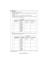
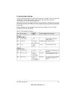
Table 12 depicts the use of relay outputs for different settings of parameters 1401 and 1402. If Autochange
function is not used, first relay output configured for PFC use controls the speed regulated motor. If
Autochange function is used, the ACS 400 Autochange logic assigns the relay outputs to corresponding
motors (of which one is speed controlled).
Table 12
Usage of relay outputs. Relay output configuration is set by parameters 1401, 1402 and 8117.
Number of relay outputs needed depends on the number of auxiliary motors. For example, if the number of
auxiliary motors is 2, total of three relay outputs (motors 1,2 and 3) are needed. x = Any setting other than
29 (PFC).
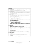
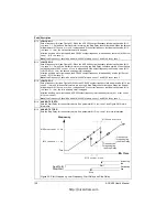
8118
AUTOCHNG INTERV
Sets the interval for the Autochange function. The time is counted only when the ACS 400 Start signal is on.
See parameter 8119
AUTOCHNG
LEVEL
for information on the operation of the Autochange.
0.0 =
NOT
SEL
This setting switches off the Autochange function.
Note! The ACS 400 always coasts to stop when autochange is performed.
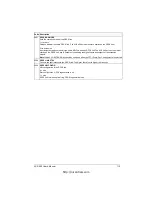
Warning
!
If the Autochange function is used, the Interlocks must be in use. In the Autochange system there
is a contactor between the ACS 400’s output terminals and the speed controlled motor. The contactor is
damaged if opened without first interrupting the ACS 400 inverter bridge switching. The inverter switching is
interrupted when the Interlock is switched off and the ACS 400 coasts to stop.
Code Description
Parameter
setting
ACS 400 relays
NDIO module 1
(Module node number
= 5)
NDIO module 2
(Module node number =
6)
1401
RELAY
OUTPUT
1
1402
RELAY
OUTPUT
2
Relay
output
RO1
function
Relay
output
RO2
function
NDIO
relay
output 1
function
NDIO
relay
output 2
function
NDIO relay
output 1
function
NDIO relay
output 2
function
29 (PFC)
29 (PFC)
Motor 1
start/stop
Motor 2
start/stop
Motor 3
start/stop
Motor 4
start/stop
Not used
Not used
29 (PFC)
x
Motor 1
start/stop
e.g. Fault
Motor 2
start/stop
Motor 3
start/stop
Motor 4
start/stop
Not used
x
29 (PFC)
e.g. Fault
Motor 1
start/stop
Motor 2
start/stop
Motor 3
start/stop
Motor 4
start/stop
Not used
x
x
e.g. Run
e.g. Fault
Motor 1
start/stop
Motor 2
start/stop
Motor 3
start/stop
Motor 4
start/stop
http://nicontrols.com
Содержание ACS 400
Страница 3: ...http nicontrols com ...
Страница 5: ...http nicontrols com ...
Страница 7: ...iv ACS 400 User s Manual http nicontrols com ...
Страница 45: ...34 ACS 400 User s Manual http nicontrols com ...
Страница 52: ...ACS 400 User s Manual 41 Motor Will Not Run http nicontrols com ...
Страница 53: ...42 ACS 400 User s Manual Motor Stalls during Acceleration http nicontrols com ...
Страница 54: ...ACS 400 User s Manual 43 Overvoltage Fault Indication http nicontrols com ...
Страница 55: ...44 ACS 400 User s Manual Overcurrent Fault Indication http nicontrols com ...
Страница 56: ...ACS 400 User s Manual 45 Overload Fault Indication http nicontrols com ...
Страница 57: ...46 ACS 400 User s Manual Undervoltage Fault Indication http nicontrols com ...
Страница 58: ...ACS 400 User s Manual 47 External Fault Indication http nicontrols com ...
Страница 59: ...48 ACS 400 User s Manual No Operator Display http nicontrols com ...
Страница 75: ...64 ACS 400 User s Manual http nicontrols com ...
Страница 161: ...150 ACS 400 User s Manual http nicontrols com ...
Страница 167: ...156 ACS 400 User s Manual http nicontrols com ...
Страница 177: ...166 ACS 400 User s Manual http nicontrols com ...
Страница 179: ...168 ACS 400 User s Manual ACS 400 NEMA Type 1 Enclosure R2 Frame Size http nicontrols com ...
Страница 180: ...ACS 400 User s Manual 169 ACS 400 NEMA Type 1 Enclosure R3 Frame Size http nicontrols com ...
Страница 181: ...170 ACS 400 User s Manual ACS 400 NEMA Type 1 Enclosure R4 Frame Size http nicontrols com ...
Страница 182: ...ACS 400 User s Manual 171 ACS 400 NEMA Type 12 4 Enclosure R1 Frame Size http nicontrols com ...
Страница 183: ...172 ACS 400 User s Manual ACS 400 NEMA 12 4 Enclosure R2 Frame Size http nicontrols com ...
Страница 184: ...ACS 400 User s Manual 173 ACS 400 NEMA Type 12 4 R3 Frame Size http nicontrols com ...
Страница 185: ...174 ACS 400 User s Manual ACS 400 NEMA Type 12 4 R4 Frame Size http nicontrols com ...
Страница 186: ...http nicontrols com ...