


36
ACS 400 User’s Manual
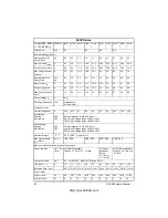
Table 5 Alarms
Alarm
Code
Display
Description
1 *
OPERATION
FAILED
Parameter upload or download failed. The software versions of the drives may
not be compatible. Software version can be seen from parameter 3301
SOFTWARE
VERSION
.
2 *
START
ACTIVE
Control panel function is not allowed while start is active.
3 *
LOCAL
/
REMOTE
Control panel function is not allowed in current control mode (local or remote).
Control mode is local when LOC is displayed and remote mode when REM is
displayed on the control panel.
5 *
BUTTON
DISABLED
Control panel function is denied for any of the following reasons:
•
START/STOP button is interlocked from digital input. This can happen with
certain digital input configurations. Refer to chapter Application Macros.
•
REVERSE button is locked because shaft direction is fixed by parameter
1003
DIRECTION
.
•
The drive is in remote control mode and START/STOP and REVERSE
buttons are not followed.
6 *
PARAM
/
LOCAL
LOCK
Control panel function is not allowed:
•
Parameter 1602
PARAMETER
LOCK
denies parameter editing
•
Parameter 1605
LOCAL
LOCK
denies local control mode.
7 *
FACTORY
MACRO
Control panel function is not allowed: Factory macro is selected and denies the
parameter modifications. Factory macro is intended for applications where
there is no control panel available.
10 **
OVERCURRENT
Overcurrent controller is active.
11 **
OVERVOLTAGE
Overvoltage controller is active.
12 **
DC
UNDERVOLTAGE
Undervoltage controller is active.
13
DIRECTION
LOCK
Rotation direction if fixed by parameter 1003
DIRECTION
.
14
SERIAL
COMM
LOSS
Serial communication through Standard Modbus Channel is lost.
•
Check connections between the external control system and the ACS 400.
•
Refer to parameters 5003
COMM
FAULT
TIME
and 5004
COMM
FAULT
FUNC
.
15 *, **
MODBUS
EXCEPTION
Exception response is sent through Standard Modbus channel. The bus master
may be sending queries which cannot be processed by the ACS 400. Refer to
“Standard Serial Communication” section.
Last three exception response codes are stored into parameters 5213 - 5215.
16
AI
1
LOSS
Analog input 1 loss. Analog input 1 value is less than
MINIMUM
AI1 (1301). See
also parameter 3001
AI
<
MIN
FUNCTION
.
17
AI
2
LOSS
Analog input 2 loss. Analog input 2 value is less than
MINIMUM
AI2 (1306). See
also parameter 3001
AI
<
MIN
FUNCTION
.
18
PANEL
LOSS
Panel communication loss. Control panel is disconnected when
- Drive is in local control mode (LOC is shown in the control panel display), or
- Drive is in remote control mode (REM) and is parameterised to accept start/
stop, direction or reference from the panel. Refer to parameters in groups 10
COMMAND INPUTS and 11 REFERENCE SELECT.
See also parameter 3002
PANEL
LOSS
.
19 **
ACS
400
OVERTEMP
ACS 400 overtemperature condition. This alarm is given when the temperature
reaches 95% of the trip limit.
20
MOTOR
OVERTEMP
Motor overtemperature condition as estimated by the ACS 400. Refer to
parameters 3004 – 3008.
21
UNDERLOAD
Motor load is too low. Check for a problem in the driven equipment. Refer to
parameters 3013 – 3015.
22
MOTOR
STALL
Motor is operating in the stall region. This may be caused by excessive load or
insufficient motor power. Refer to parameters 3009 – 3012.
http://nicontrols.com
Содержание ACS 400
Страница 3: ...http nicontrols com ...
Страница 5: ...http nicontrols com ...
Страница 7: ...iv ACS 400 User s Manual http nicontrols com ...
Страница 45: ...34 ACS 400 User s Manual http nicontrols com ...
Страница 52: ...ACS 400 User s Manual 41 Motor Will Not Run http nicontrols com ...
Страница 53: ...42 ACS 400 User s Manual Motor Stalls during Acceleration http nicontrols com ...
Страница 54: ...ACS 400 User s Manual 43 Overvoltage Fault Indication http nicontrols com ...
Страница 55: ...44 ACS 400 User s Manual Overcurrent Fault Indication http nicontrols com ...
Страница 56: ...ACS 400 User s Manual 45 Overload Fault Indication http nicontrols com ...
Страница 57: ...46 ACS 400 User s Manual Undervoltage Fault Indication http nicontrols com ...
Страница 58: ...ACS 400 User s Manual 47 External Fault Indication http nicontrols com ...
Страница 59: ...48 ACS 400 User s Manual No Operator Display http nicontrols com ...
Страница 75: ...64 ACS 400 User s Manual http nicontrols com ...
Страница 161: ...150 ACS 400 User s Manual http nicontrols com ...
Страница 167: ...156 ACS 400 User s Manual http nicontrols com ...
Страница 177: ...166 ACS 400 User s Manual http nicontrols com ...
Страница 179: ...168 ACS 400 User s Manual ACS 400 NEMA Type 1 Enclosure R2 Frame Size http nicontrols com ...
Страница 180: ...ACS 400 User s Manual 169 ACS 400 NEMA Type 1 Enclosure R3 Frame Size http nicontrols com ...
Страница 181: ...170 ACS 400 User s Manual ACS 400 NEMA Type 1 Enclosure R4 Frame Size http nicontrols com ...
Страница 182: ...ACS 400 User s Manual 171 ACS 400 NEMA Type 12 4 Enclosure R1 Frame Size http nicontrols com ...
Страница 183: ...172 ACS 400 User s Manual ACS 400 NEMA 12 4 Enclosure R2 Frame Size http nicontrols com ...
Страница 184: ...ACS 400 User s Manual 173 ACS 400 NEMA Type 12 4 R3 Frame Size http nicontrols com ...
Страница 185: ...174 ACS 400 User s Manual ACS 400 NEMA Type 12 4 R4 Frame Size http nicontrols com ...
Страница 186: ...http nicontrols com ...