


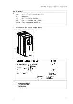

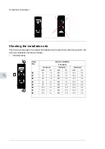
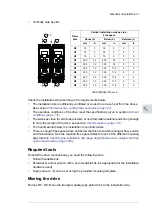
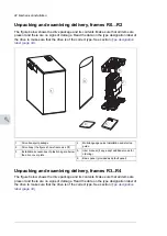
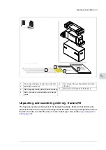


■
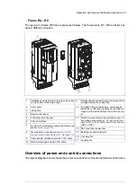
Frame R4…R8
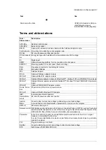
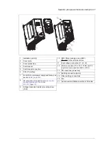
The layout of a frame R6 drive is presented below. The frame sizes R7…R8 is similar but
have a different structure.
2
3
4
5
6
7
8
11
12
13
10
10
3
16
15
1
9
12
PE
17
14
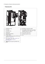
1
Voltage dependent resistor ground screw (VAR),
arranged below the control tray.
11
Two EMC filter ground screws, one arranged
below the control tray bracket and the other ar-
ranged on the left and above the protective cov-
er.
12
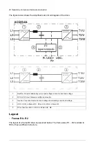
Protective cover. Below the protective cover: in-
put voltage connection (L1, L2, L3), motor con-
nection (T1/U, T2/V, T3/W) and DC connection
(UDC+, UDC-).
13
PE connection (power line)
14
Earthing connection (motor)
15
A primary fan
16
Auxiliary fan
17
Installation point (2 points on the top and 2 points
on the bottom of the frame body)
1
Cover plate
2
Lifting hole
3
Basic control panel
4
Control panel connection
5
CCA-01 interface
6
For LED of normal power supply and failure, see
section
7
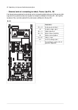
I/O connection. See section
connection terminals, frames R6…R8 (page 32)
8
Cable bundle installation position of I/O cable
9
Mechanical support clamp of I/O cable
10
Overview of power and control connections
The logical diagram below shows the power connections and control interfaces of the drive.
Operation principle and hardware description 29
Содержание ACQ80-04 Series
Страница 1: ...ABB DRIVES FOR WATER ACQ80 04 drives 0 75 to 160 kW 1 0 to 215 hp Hardware manual...
Страница 2: ......
Страница 4: ......
Страница 18: ...18...
Страница 23: ...ACQ80 04 manuals See www abb com drives documents for all manuals on the internet Introduction to the manual 23...
Страница 24: ...24...
Страница 38: ...38...
Страница 50: ...50...
Страница 64: ...64...
Страница 98: ...98...
Страница 110: ...110...
Страница 140: ...Frame R3 IP20 140 Dimension drawings...
Страница 146: ...146...
Страница 162: ...162...
Страница 168: ......


