

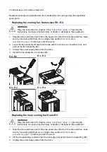


2.
To remove the battery, use a coin to rotate the battery cover on the back of the control
panel.
3.
Replace the battery with type CR2032. Dispose the old battery according to local disposal
rules or applicable laws.
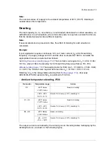
118 Maintenance and hardware diagnostics
Control panel
Cleaning the control panel
Use a soft damp cloth to clean the control panel. Avoid harsh cleaners which could
scratch the display window.
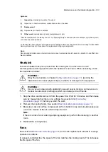
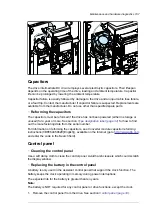
Replacing the battery in the control panel
A battery is only used in the assistant control panel that support the clock function.
The battery keeps the clock operating in memory during power interruptions.
The expected life for the battery is greater than ten years.
Note:
The battery is NOT required for any control panel or drive functions, except the
clock.
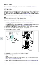
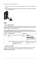
1. Remove the control panel from the drive. See section
Control panel
on page
34
.
2. To remove the battery, use a coin to rotate the battery cover on the back of the
control panel.
3. Replace the battery with type CR2032. Dispose the old battery according to local
disposal rules or applicable laws.
CR2032
2
LEDs
■
Drive LEDs (R3~R8)
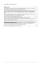
There is a green POWER and a red FAULT LED on the front of the drive. They are visible
through the panel cover but invisible if a control panel is attached to the drive. The table
below describes the drive LED indications.
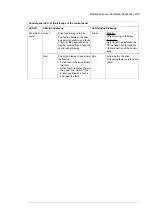
Drive LEDs POWER and FAULT, on the front of the drive, under the control panel / panel cover
If a control panel is attached to the drive, switch to remote control (otherwise a fault will be generated),
and then remove the panel to be able to see the LEDs
LED blinking
LED lit and steady
LEDs off
Blinking:
Drive in an alarm state
Green
(POWER)
Power supply on the board OK
Green
(POWER)
No power
Blinking for one second:
Drive selected on the control
panel when multiple drives are
connected to the same panel
bus.
Active fault in the drive. To reset
the fault, switch off the drive
power.
Red (FAULT)
Active fault in the drive. To reset
the fault, press RESET from the
control panel or switch off the
drive power.
Red (FAULT)
■
Control panel LEDs
The basic control panel has one LED. The table below describes the control panel LED
indications. For more information see ACS-BP-S basic control panel user manual
(3AXD50000032527 [English]).
108 Maintenance and hardware diagnostics
Содержание ACQ80-04 Series
Страница 1: ...ABB DRIVES FOR WATER ACQ80 04 drives 0 75 to 160 kW 1 0 to 215 hp Hardware manual...
Страница 2: ......
Страница 4: ......
Страница 18: ...18...
Страница 23: ...ACQ80 04 manuals See www abb com drives documents for all manuals on the internet Introduction to the manual 23...
Страница 24: ...24...
Страница 38: ...38...
Страница 50: ...50...
Страница 64: ...64...
Страница 98: ...98...
Страница 110: ...110...
Страница 140: ...Frame R3 IP20 140 Dimension drawings...
Страница 146: ...146...
Страница 162: ...162...
Страница 168: ......


