


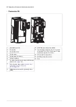


■
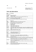
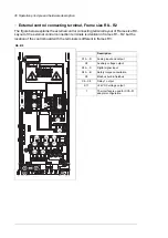
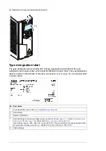
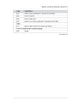
External control connecting terminal, Frame size R3...R5
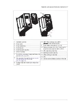
The figure below explains the external control connecting terminal layout of Frame size R3.
Description
X5
X4
X1
X2
X3
X14
X6
X7
X8
X13
Analog input and output
X1
Auxiliary voltage output
X2
Digital input
X3
Safety torque cancellation
X4
Modbus built-in fieldbus
X5
Relay output 1...Relay output 3
X6…X8
Option slot 1 (fieldbus adapter
module)
X13
Option slot 2 (not used)
X14
Panel port (control panel connec-
tion)
1
The interface is used for CCA-01
adapter configuration
2
For LED of normal power supply
and failure, see section
3
Operation principle and hardware description 31
Содержание ACQ80-04 Series
Страница 1: ...ABB DRIVES FOR WATER ACQ80 04 drives 0 75 to 160 kW 1 0 to 215 hp Hardware manual...
Страница 2: ......
Страница 4: ......
Страница 18: ...18...
Страница 23: ...ACQ80 04 manuals See www abb com drives documents for all manuals on the internet Introduction to the manual 23...
Страница 24: ...24...
Страница 38: ...38...
Страница 50: ...50...
Страница 64: ...64...
Страница 98: ...98...
Страница 110: ...110...
Страница 140: ...Frame R3 IP20 140 Dimension drawings...
Страница 146: ...146...
Страница 162: ...162...
Страница 168: ......


