


■
Connection procedure, frames R3...R4
WARNING!
WARNING!
If the drive is connected on an IT (ungrounded) system, make sure you have
disconnected the EMC Filter and Varistor (VAR). See
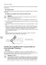
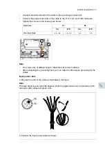
1. Remove the front cover as follows:
•
Loosen the retaining screw with a screwdriver (1a).
•
Push the front cover upward to uncouple top buckle (1b), and lift the cover from the
bottom outwards (1c).
82 Electrical installation
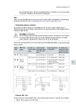
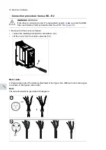
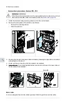
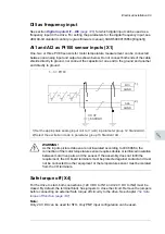
Connection procedure, frames R3…R4
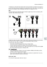
1. Remove the front cover as follows:
•
Loosen the retaining screw with a screwdriver (1a).
•
Push the front cover upward to uncouple top buckle (1b), and lift the cover
from the bottom outwards (1c).
Warning!
If the drive will be connected on an IT (ungrounded) system, make
sure you have disconnected the EMC Filter and Varistor (VAR). See page
71
.
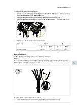
Motor cable
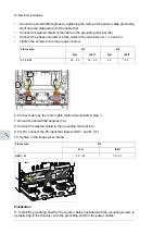
2. Prepare the ends of the cable as illustrated in the figure. Two different motor cable
types are shown in the figures 2a and 2b.
Note:
The bare shield will be grounded 360 degrees.
2a
1C
1b
2a
PE
PE
2b
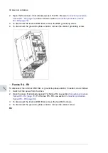
Motor cable
2. Prepare the ends of the cable as illustrated in the figure. Two different motor cable types
are shown in the figures 2a and 2b.
Note:
The bare shield will be grounded 360 degrees.
78 Electrical installation
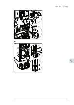
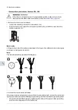
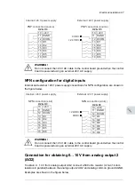
Connection procedure, frames R0…R2
1. Remove the front cover as follows:
•
Loosen the retaining screw with a screwdriver (1a).
•
Lift the cover from the bottom outwards (1b).
Warning!
If the drive is connected on an IT (ungrounded) system, make sure
that the EMC Filter and Varistor (VAR) is disconnected. See page
71
.
Motor cable
2. Prepare the ends of the cable as illustrated in the figure. Two different motor cable
types are shown in the figures (2a.and 2b).
Note:
The bare shield will be grounded 360 degrees.
1a
1b
2a
PE
PE
2
b
78 Electrical installation
Connection procedure, frames R0…R2
1. Remove the front cover as follows:
•
Loosen the retaining screw with a screwdriver (1a).
•
Lift the cover from the bottom outwards (1b).
Warning!
If the drive is connected on an IT (ungrounded) system, make sure
that the EMC Filter and Varistor (VAR) is disconnected. See page
71
.
Motor cable
2. Prepare the ends of the cable as illustrated in the figure. Two different motor cable
types are shown in the figures (2a.and 2b).
Note:
The bare shield will be grounded 360 degrees.
1a
1b
2a
PE
PE
2
b
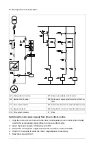
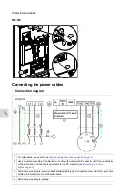
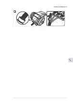
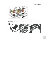
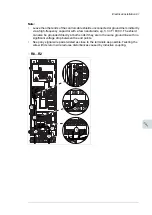
3. Connect the motor cable as follows:
If the power cable is temporarily removed from the grounding shelf, connect the motor and
input power cables except the 360 degree grounding, and then reinstall the grounding shelf.
•
Ground the shield 360 degrees by tightening the clamp of the power cable grounding
shelf onto the stripped part of the cable (4a).
76 Electrical installation
Содержание ACQ80-04 Series
Страница 1: ...ABB DRIVES FOR WATER ACQ80 04 drives 0 75 to 160 kW 1 0 to 215 hp Hardware manual...
Страница 2: ......
Страница 4: ......
Страница 18: ...18...
Страница 23: ...ACQ80 04 manuals See www abb com drives documents for all manuals on the internet Introduction to the manual 23...
Страница 24: ...24...
Страница 38: ...38...
Страница 50: ...50...
Страница 64: ...64...
Страница 98: ...98...
Страница 110: ...110...
Страница 140: ...Frame R3 IP20 140 Dimension drawings...
Страница 146: ...146...
Страница 162: ...162...
Страница 168: ......


