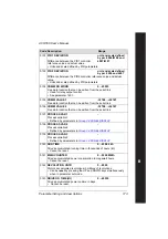

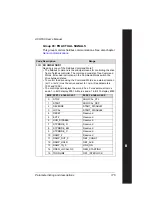
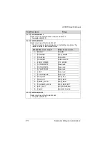


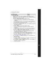


Parameter listing and descriptions
187
ACH550 User's Manual
4 =
AI
2/
JOYST
– Defines analog input 2 (
AI
2), configured for joystick
operation, as the reference source.
• See above (
AI
2/
JOYST
) description.
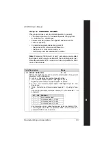
5 =
DI
3
U
,4
D
(
R
) – Defines digital inputs as the speed reference source
(motor potentiometer control).
• Digital input
DI
3 increases the speed (the
U
stands for “up”).
• Digital input
DI
4 decreases the speed (the
D
stands for “down”).
• A Stop command resets the reference to zero (the
R
stands for
“reset”).
• Parameter 2205
ACCELER
TIME
2 controls the reference signal’s rate
of change.
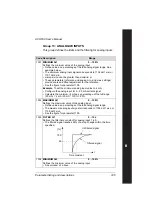
6 =
DI
3
U
,4
D
– Same as above (
DI
3
U
,4
D
(
R
)), except:
• A Stop command does not reset the reference to zero. The
reference is stored.
• When the drive restarts, the motor ramps up (at the selected
acceleration rate) to the stored reference.
7 =
DI
5
U
,6
D
– Same as above (
DI
3
U
,4
D
), except that
DI
5 and
DI
6 are the
digital inputs used.
8 =
COMM
– Defines the fieldbus as the reference source.
9 =
COMM
+
AI
1 – Defines a fieldbus and analog input 1 (
AI
1) combination
as the reference source. See
Analog input reference correction
page
.
10 =
COMM
*
AI
1 – Defines a fieldbus and analog input 1 (
AI
1)
combination as the reference source. See
on page
.
11 =
DI
3
U
, 4
D
(
RNC
) – Same as
DI
3
U
,4
D
(
R
) above, except that:
• Changing the control source (
EXT
1 to
EXT
2,
EXT
2 to
EXT
1,
LOC
to
REM
) does not copy the reference.
12 =
DI
3
U
,4
D
(
NC
) – Same as
DI
3
U
,4
D
above, except that:
• Changing the control source (
EXT
1 to
EXT
2,
EXT
2 to
EXT
1,
LOC
to
REM
) does not copy the reference.
13 =
DI
5
U
,6
D
(
NC
) – Same as
DI
3
U
,4
D
above, except that:
• Changing the control source (
EXT
1 to
EXT
2,
EXT
2 to
EXT
1,
LOC
to
REM
) does not copy the reference.
14 =
AI
1+
AI
2 – Defines an analog input 1 (
AI
1) and analog input 2 (
AI
2)
combination as the reference source. See
on page
.
15 =
AI
1*
AI
2 – Defines an analog input 1 (
AI
1) and analog input 2 (
AI
2)
combination as the reference source. See
on page
.
16 =
AI
1-
AI
2 – Defines an analog input 1 (
AI
1) and analog input 2 (
AI
2)
combination as the reference source. See
on page
.
17 =
AI
1/
AI
2 – Defines an analog input 1 (
AI
1) and analog input 2 (
AI
2)
combination as the reference source. See
on page
.
Code Description
Range
Содержание ACH550-01
Страница 1: ...ACH550 User s Manual ACH550 01 Drives 0 75 110 kW ACH550 UH Drives 1 150 HP ABB ...
Страница 10: ...Update Notice 8 ...
Страница 12: ......
Страница 18: ...6 ACH550 User s Manual ...
Страница 50: ...38 Preparing for installation ACH550 User s Manual ...
Страница 325: ...313 ACH550 User s Manual ...
Страница 358: ...346 ACH550 User s Manual ...
Страница 409: ...Technical data 397 ACH550 User s Manual Frame size R1 IP54 UL Type 12 ...
Страница 410: ...398 Technical data ACH550 User s Manual Frame size R2 IP54 UL Type 12 ...
Страница 411: ...Technical data 399 ACH550 User s Manual Frame size R3 IP54 UL Type 12 ...
Страница 412: ...400 Technical data ACH550 User s Manual Frame size R4 IP54 UL Type 12 ...
Страница 413: ...Technical data 401 ACH550 User s Manual Frame size R5 IP54 UL Type 12 ...
Страница 414: ...402 Technical data ACH550 User s Manual Frame size R6 IP54 UL Type 12 ...
Страница 415: ...Technical data 403 ACH550 User s Manual Frame size R1 IP21 UL Type 1 ...
Страница 416: ...404 Technical data ACH550 User s Manual Frame size R2 IP21 UL Type 1 ...
Страница 417: ...Technical data 405 ACH550 User s Manual Frame size R3 IP21 UL Type 1 ...
Страница 418: ...406 Technical data ACH550 User s Manual Frame size R4 IP21 UL Type 1 ...
Страница 419: ...Technical data 407 ACH550 User s Manual Frame size R5 IP21 UL Type 1 ...
Страница 420: ...408 Technical data ACH550 User s Manual Frame size R6 IP21 UL Type 1 ...
Страница 453: ......


