


The terminals 1.8, 2.8, 3.8, 4.8, 1.9, 2.9, 3.9 and 4.9 are electrically interconnected within the
I/O terminal units and always have the same assignment, independent of the inserted module:
Terminals 1.8, 2.8, 3.8 and 4.8: process voltage UP = +24 VDC
Terminals 1.9, 2.9, 3.9 and 4.9: process voltage ZP = 0 V
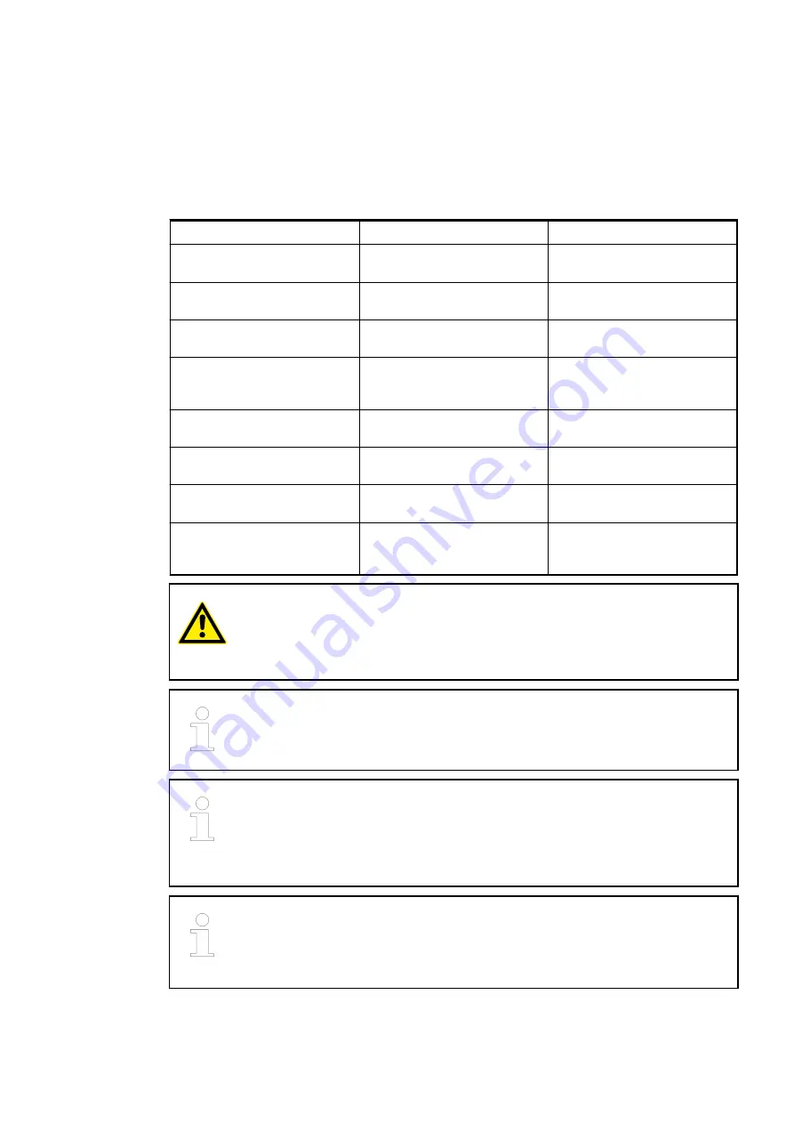
The assignment of the other terminals:
Terminals
Signal
Description
2.0, 2.2, 2.4, 2.6
I0+ to I3+
Positive poles of the first 4
analog inputs
1.0, 1.2, 1.4, 1.6
I0- to I3-
Negative poles of the first 4
analog inputs
2.1, 2.3, 2.5, 2.7
I0A to I3A
Connections A (supply) of the
first 4 analog inputs
1.1, 1.3, 1.5, 1.7
I0B to I3B
Connections B (analog
ground) of the first 4 analog
inputs
4.0, 4.2, 4.4, 4.6
I4+ to I7+
Positive poles of the following
4 analog inputs
3.0, 3.2, 3.4, 3.6
I4- to I7-
Negative poles of the fol-
lowing 4 analog inputs
4.1, 4.3, 4.5, 4.7
I4A to I7A
Connections A (supply) of the
following 4 analog inputs
3.1, 3.3, 3.5, 3.7
I4B to I7B
Connections B (analog
ground) of the following 4
analog inputs
CAUTION!
Analog sensors must be electrically isolated against the earth. In order to avoid
inaccuracy with the measuring results, the analog sensors should also be iso-
lated against the power supply.
The "IxB" clamps (x=0..7) of the analog inputs are electrically connected to each
other. They form an "Analog Ground Signal" (AGND) for the module.
The negative poles of the analog inputs Ix- may accept a potential difference up
to
±
20 VDC with regard to the common reference potential IxB (AGND, ZP).
Observing this maximum voltage difference, analog current inputs of one
module can be switched in series to each other and also with current inputs of
other modules.
For the open-circuit detection (cut wire), each positive analog input channel Ix+
is pulled up to "plus" by a high-resistance resistor and each negative analog
input channel Ix- is pulled down to "minus" by a resistor. If cut wire occurs, a
maximum voltage (overflow or underflow) will be read in then.
The internal power supply voltage for the module's circuitry is carried out via the I/O bus (pro-
vided by a bus module or a CPU). Thus, the current consumption from 24 VDC power supply at
the terminals L+/UP and M/ZP of the CPU/bus module increases by 2 mA per AI531.
Device Specifications
I/O Modules > Analog I/O Modules
2019/04/17
3ADR010121, 13, en_US
474