TMC-4 Control Card
for Electric Actuators
Installation & Maintenance Manual
17
04/06/22
www.atcontrols.com
IOM08139 REVISION 04
4. Setup and Calibration
4.1.
Positioning Devices
4.1.1. Feedback Potentiometer (P7)
A feedback potentiometer connected to header (P7) is used to
detect the position of the actuator between the 0% to 100%
limits for modulating and proportional control applications. The
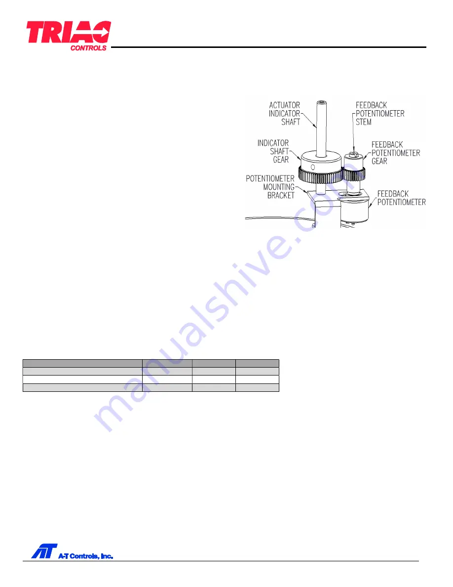
feedback potentiometer is typically coupled to the actuator
output indicator shaft by a set of gears.
To ensure the potentiometer remains within its limits through the
actuator operating range, the actuator should first be moved to
the halfway, or 50%, position. The feedback potentiometer is
then adjusted to the midpoint of its effective electrical range. For
example, a 1kΩ potentiometer should be adjusted to 500Ω. If
the potentiometer jumps from one end to another within the
actuator’s operation range, for example 0Ω to 1000Ω, the TMC4
may not be able to position correctly.
The potentiometer resistance is translated into a 12 bit count value of 0 to 4095 by the TMC4, and displayed in the
“Calibrate Close Pos” or “Calibrate Open Pos” settings in the
POSITION CONFIG
submenu. When the feedback
potentiometer is at its midpoint, the digital count value shown in either setting will be 2048, as this is the midpoint value
between the limits of 0 and 4095.
It is not critical to adjust the potentiometer to exactly 2048 at the 50% position but should be close so that the value will
not jump between the extremes of 0 and 4095 within the operating range. Centering the potentiometer approximately
between 1900-2200 should be sufficient for most applications.
The effective electrical angle of the potentiometer, actuator rotation angle, and ratio of the feedback gears determine the
maximum and minimum digital count values at the full open and full close positions, and the subsequent range that can be
expected. Typical digital count values are shown below for different gearing ratios or operating angles with the 50%
position set exactly to a value of 2048.
Gear Ratio / Actuator Rotation
Minimum
Maximum
Range
1:1 / 90°
1506
2590
1084
1:1 / 180° or 2:1 / 90°
964
3132
2168
1:1 / 270° or 3:1 / 90°
422
3674
3252
Note that the maximum and minimum values could be swapped depending on the rotation direction of the potentiometer
in relation to the rotation direction of the actuator. The TMC4 will correctly interpret the readings when positions are
calibrated. It is also not important to fall exactly at the values shown as long as the range of operation does not permit the
digital count value to jump from 0 to 4095, or vice versa. However, as the gear ratio or actuator rotation angle increases,
and the range increases, the allowance for deviation is reduced.


