12
A3-P
4.7.2 Wedge guide head replacement to change Wedges size
The wedge guide head must be changed each time you use wedges of different sizes. Proceed as follows to
replace it:
• Loosen the locking screw of the wedge guide head using the proper
5 mm Allen wrench (the screw is on the opposite side from the
wedges magazine(See fig. 10)
• Take out the wedge guide head
• Move the clawpusher backwards by flipping the special lever
located on the right side of the machine working bench (see fig. 7).
• Remove all the wedges that are still in the magazine (using the
proper brass magnet, if necessary).
• Insert the new wedge strip (of desired height) into the magazine
• Move the clawpusher forward by flipping the control lever (see
figure 7).
• Insert the new size wedge guide head to match the wedges you
will be using (see fig. 11).
• Tighten the locking screw of the wedge guide head (see fig.10).
Picture 10
Picture 11
4.8 ADJUSTMENTS
4.8.1 Wedge inserting positions adjustment
To properly position the mouldings to be assembled, the A3-P is equipped with a 90° fence. The fence can be
shifted forward or backward in order to allow the proper positioning of the wedges in the moulding the fence
stops (backward and forward) can be set with precision by means of locking clamps (see fig. 13). The operator
can easily use the machine to insert wedges with extreme precision into 2 different positions (fig. 14). You can also
stop anywhere in between these two fence stops to add more wedge insertion positions.
Picture 13
Picture 14
4.8.2 Vertical clamp adjustment
The vertical clamp can be adjusted in height and position. Proceed as follows to adjust them:
Содержание A3-P
Страница 3: ...3 A3 P...
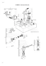
Страница 22: ...22 A3 P SCHEMES A Mechanical Schematic...
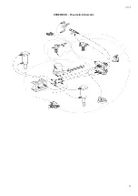
Страница 23: ...23 A3 P SCHEMES B Pneumatic Schematic...
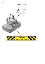
Страница 24: ...24 A3 P SCHEME C Plate locations...
Страница 26: ...26 A3 P...
Страница 27: ...27 A3 P...


