14
A1-M-XL
5. FUNCTIONING
5.1 OPERATORS
The machine has been projected to be used by only one operator.
• The operator, as well as being adequately informed on the use of machinery, must possess skills and compe-
tence adequate to the type of working activity to perform.
• Even after being adequately informed, during the first utilization, if necessary, simulate some operating ma-
noeuvres to identify the controls, especially the ones for starting and stopping the machinery and their main
functions.
• now how to operate in case of emergency , where to find the individual protection means and how to use
them properly.
5.2 FUNCTIONING DESCRIPTION
The machine has only one possible operating mode:
• Manual mechanic functioning by using the mechanical foot pedal.
Press the pedal half way to get the frames clamping
Press the pedal full down to get the Wedge ejection.
To effect a junction, you must operate as follows:
1. Set the inserting positions by means of fence locking clamps (see pict. 10)
2. Lean the mouldings on the working bench positioning the fence on the first inserting point
3. Adjust the vertical clamp height and position (see pict. 12-13)
4. Lock the B lever (see pict. 10)
5. Press half way down the pedal to verify the mouldings proper position and holding
6. Press the pedal full down to insert the Wedge. If you want to insert 2 or more Wedges one upon the other in
the same position, you must release the pedal until half of its stroke and then press again it full down to insert
the second Wedge and so on.
7. Release completely the foot pedal
8. Loosen the B lever (see pict. 10)
9. Shift the mouldings and the fence on the next inserting point and repeat the steps 4,5 and 6.
5.3 TIPS FOR PERFECT JUNCTIONS
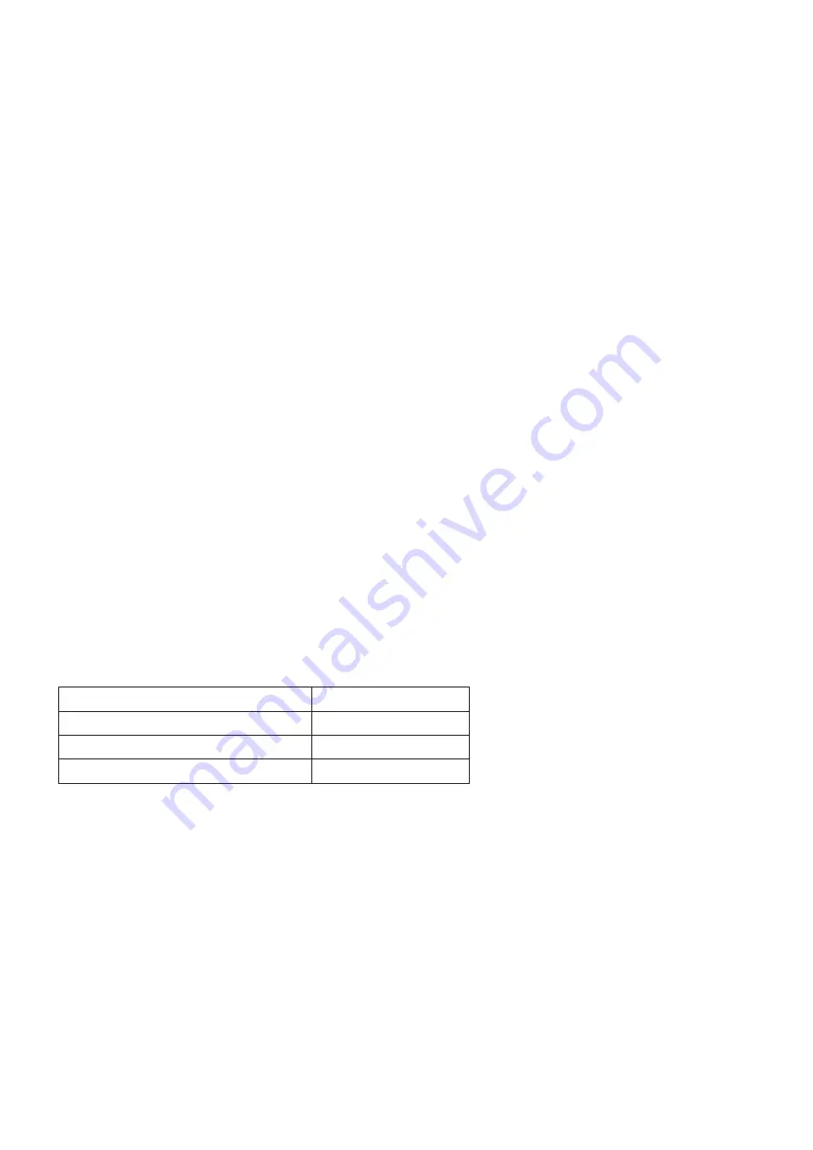
a) Wedge types
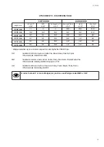
In order to allow the machine to make excellent quality joints using different materials, it has been necessary to
manufacture different Wedges types for different uses (see attachment B).
Wedges can be classified in three different groups:
Material
Suggested code
soft materials (wood, soft plastic)
SW (green)
for medium materials (wood, ...)
MW (gray)
for hard materials (wood, MDF, HDF)
HW (red)
b) Assembling positions
It is advisable to operate as follows in order to achieve the best results in terms of junction quality:
• Never drive Wedges near the junction vertex. The minimum recommended distance from the external vertex
is at least 10 mm.
• When you want to make the junction using only one Wedge, the most suitable position is in the middle of the
moulding (see pict. 14)
• In case you want to insert 2 or more Wedges into each junction, we recommend you to insert the most external
one
1
/
3
from the external vertex and the most internal one
1
/
4
from the internal vertex.
Содержание A1-M-XL
Страница 3: ...3 A1 M XL...
Страница 20: ...20 A1 M XL SCHEMES B Mechanic Schemes A1 M XL P R E L I M I N A R Y...
Страница 21: ...21 A1 M XL SCHEMES B Mechanic Schemes A1 M...
Страница 22: ...22 A1 M XL...
Страница 23: ...23 A1 M XL...
Страница 24: ......


