Product Options | 281
Aprisa SRx User Manual 1.3.0
Creating a Protected Station
When a Protected Station is ordered from 4RF, it will be delivered complete with radios installed, pre-
cabled and pre-configured for Redundant operation. The following process will not be required.
This process is to create a protected station from two individual Aprisa SR+ radios and a new spare Aprisa
SR+ Protection Switch. It assumes that the Aprisa SR+ radios are currently setup for non-protected
operation.
1. Set the protection type and partner IP address of the Aprisa SR+ radio A with SuperVisor 'Terminal >
Operating Mode'. Set this radio Protection Unit to primary.
2. Set the protection type and partner IP address of the secondary Aprisa SR+ radio B with SuperVisor
Terminal > Operating Mode'. Set this radio Protection Unit to secondary.
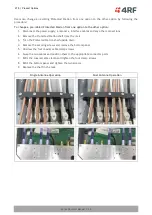
3. Switch off the radios and place the two radios in the new spare Aprisa SR+ Protection Switch.
4. Ensuring that the cables are not crossed over, plug in the interface port cables, the Alarm and Protect
port cables and the power connector to both the radios. Secure the power connectors with the two
screws.
5. Power on the Protected Station.
6. Connect to either one of the radios via SuperVisor. This will start up SuperVisor in Single Session
Management mode.
7. The user can now configure the Protected Station as required.
Replacing a Protected Station Faulty Radio
Replacing a faulty radio in a Protected Station can be achieved without disruption to traffic.
Assuming that the primary radio is active and the secondary radio is faulty and needs replacement:
1. Ensure the replacement radio has the same version of software installed as the primary radio. If
necessary, upgrade the software in the replacement radio.
2. Set the RF Interface MAC Address (see ‘Protected Station: Maintenance > Advanced’ on page 238).
This MAC address is present on chassis label.
3. Using SuperVisor > Maintenance > Advanced ‘Save Configuration to USB’ and ‘Restore Configuration
from USB’ operation, clone the primary radio’s configuration to the replacement radio.
4. Configure the replacement radio as the secondary radio and setup the IP address and other protection
parameters (see ‘Terminal > Operating Mode’ on page 87).
5. Set the Hardware Manual Lock switch to make the primary radio active.
6. Unplug the interface port cables, the Alarm and Protect port cables and the power connector from the
faulty radio being replaced. The two screws securing the power connector will need to be undone.
7. Carefully remove the faulty radio from the protection switch.
8. Install the replacement radio into the protection switch.
9. Ensuring that the cables are not crossed over, plug in the interface port cables, the Alarm and Protect
port cables and the power connector to the replacement radio. Secure the power connector with the
two screws.
10. Power on the replacement radio and wait for it to become standby.
11. Set the Hardware Manual Lock switch to the Auto position.

