About the Radio | 25
Aprisa SRx User Manual 1.3.0
Performance
Typical deployment of 30 remote stations from one base station with a practical limit of a few
hundred remote stations
Long distance operation
High transmit power
Low noise receiver
Forward Error Correction
Electronic tuning over the frequency band
Thermal management for high power over a wide temperature range
Usability
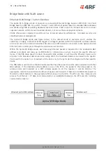
Configuration / diagnostics via front panel Management Port USB interface, Ethernet interface
Built-in webserver SuperVisor with full configuration, diagnostics and monitoring functionality,
including remote station configuration / diagnostics over the radio link
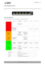
LED display for on-site diagnostics
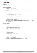
Dedicated alarm port
Software upgrade and diagnostic reporting via the host port USB flash drive
Over-the-air software distribution and upgrades
Simple installation with integrated mounting holes for wall, DIN rail and rack shelf mounting
System Gain vs FEC Coding
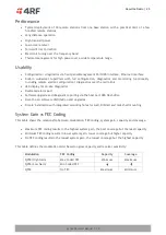
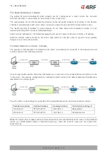
This table shows the relationship between modulation, FEC coding, system gain, capacity and coverage.
Maximum FEC coding results in the highest system gain, the best coverage but the least capacity
Minimum FEC coding results in lower system gain, lower coverage but higher capacity
No FEC coding results in the lowest system gain, the lowest coverage but the highest capacity
This table defines the modulation order based on gross capacity and receiver sensitivity:
Modulation
FEC Coding
Capacity
Coverage
QPSK (High Gain)
Max Coded FEC
Minimum
Maximum
QPSK (Low Gain)
Min Coded FEC
QPSK
No FEC
Maximum
Minimum

