


VISIX SOLUTIONS | VX-2S-OP-30X QUICK START GUIDE | p.14
Lock
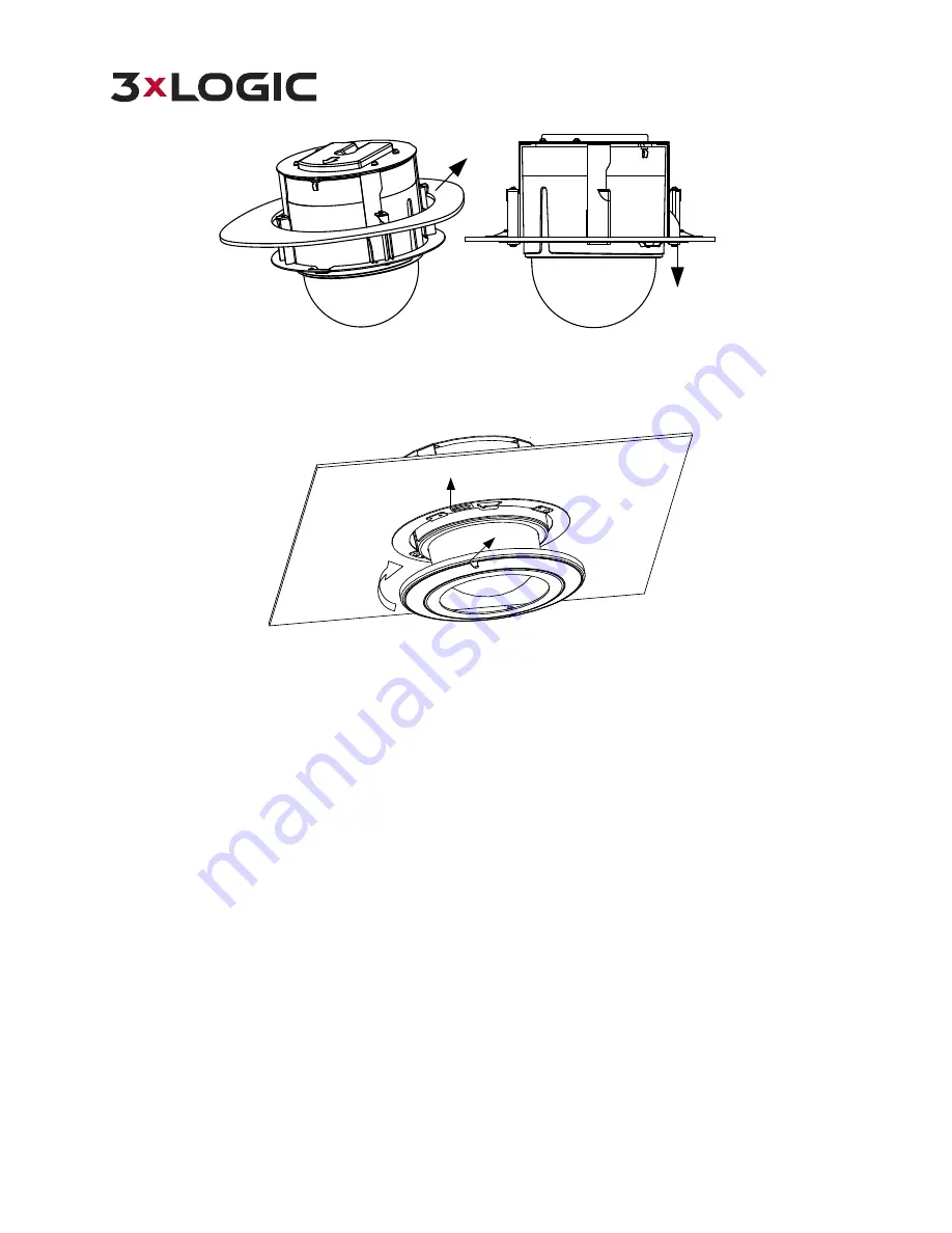
Ceiling
Figure 2-26
Install the Back Box
8.
Install the flange.
1).
Attach the flange to the bubble and align the triangular notch of the trim ring with the arrow label on the in-
ceiling bracket.
2).
Firmly place the flange against the ceiling and rotate the flange in the direction of the arrow to secure it.
Notch
Arrow Label
Figure 2-27
Install the Flange
9.
Remove the protective film on the bubble after the installation is complete.
2.6
Ceiling Mounting
2.6.1
CEILING MOUNT APPLICATION
Before you start:
The ceiling mounting is intended for indoor/outdoor solid ceilings. The following are mandatory preconditions for
ceiling mounting:
n
The thickness of the ceiling must range from 5mm to 40mm.
n
The ceiling must be strong enough to withstand more than 4 times the weight of the dome and its
accessories.
n
If the speed dome is to be fastened to a wooden ceiling, use the self-tapping screws to secure the
mounting base.
n
If the speed dome is to be fastened to a cement ceiling, drill three
Φ
5 mm screw holes into the ceiling
according to the position of the holes, and then secure the mounting base to the ceiling with expansion
screws.
2.6.2
REMOVING THE IN-CEILING MOUNT
The speed dome is installed with an in-ceiling mount by default. Before you mount the speed dome on the ceiling,
you need to remove the in-ceiling mount first.
Steps:
1.
Loosen and remove the 4 screws as shown in Figure 2-28.