User Manual
11
1. The lowest requirement for user's computer is as below:
Install operating system (Windows XP/2000/7/8,etc)
Install Ethernet card
Install Web explorer (IE6.0 or higher version)
Install and start TCP/IP protocol
2. Establish the correct network configuration
The default management IP address of the switch: 192.168.1.254, subnet mask as: 255.255.255.0.
Before access to the configuration interface, the computer's IP address and the switch must be
configured in the same subnet (IP address configuration, please refer to "5.1") if need local configuration;
Computers and switches must be routed reach if for remote configuration.
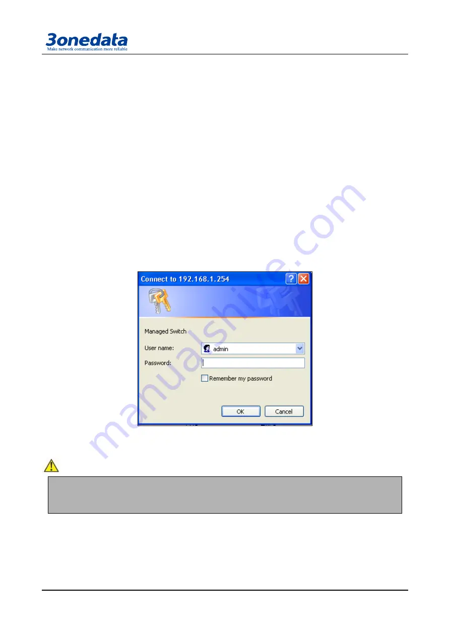
5.2 Login Web Server
Please type in the default IP of switch on the
browser‘s address bar, and then will pop-up a window by
clicking the ―enter‖ key which shows you have to enter your user name and password. The default
username and p
assword is ―admin‖. You can enter your username and password 3 times if you found the
username and password is incorrect. If the 3 input error, the browser will display a "Access denied" error
message. Refresh the page and then enter the correct user name and password, log on to the Web
Server, it will recommend to modify the user name and password. Please contact our customer service
center if you have more questions.
(Figure 5.2.1)
The default username and password is [admin], case sensitive for this series. The default password
is with administrator privileges.
:
Before entering the switch Web Server, you must delete temporary IE files, and clear IE history, or perhaps because
IE cookies due to an unknown error.
The user name and password are case sensitive. Such as unclear devices IP address, can be obtained through the
Blue_eyes management software search. (attached)
5.3 Introduction configure interface
The Web configuration page is divided into: 1 title, 2 main menu, 3 configuration menu bar area three
parts. Click the menu item in the menu bar, you can enter the corresponding configuration interface,
display device state information and data configuration. As shown in Figure 5.3.1.
Содержание IES615-1F-2DI
Страница 20: ...User Manual 16 RS 232 RS 485 RS 422 serial port Optional ...
Страница 57: ...User Manual 53 ...


