20
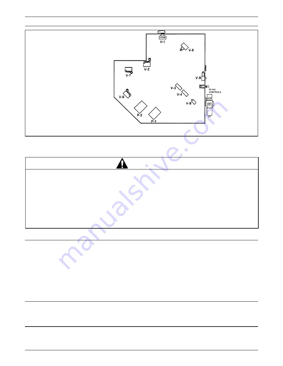
Figure 7-2 – Troubleshooting Valve Locations – S-867 Right Side View
Note: The complete pneumatic
schematic is shown in the beginning of
the Troubleshooting section, Fig. 7-1.
Troubleshooting Guide
(arranged in sequence of machine operation)
•
To reduce the risk associated with sharp blade hazards:
−
Keep hands and fingers away from tape cutoff blades under orange blade guards. The blades are extremely
sharp
•
To reduce the risk associated with mechanical and pneumatic hazards:
−
Allow only properly trained and qualified personnel to operate and/or service this equipment
•
To reduce the risk associated with pinch and entanglement hazards:
−
Turn air supply off and disconnect before performing any adjustments, maintenance or servicing the machine
WARNING
Troubleshooting
(Continued)
Problem
Possible Cause
Correction
Unit does not cycle.
Cut-off assembly does not retract.
Buffing assembly does not retract.
1. Air supply shut off or not connected
to unit.
2. Cover open.
3. Valve V-8 out of adjustment or
defective.
4. Valve V-9 out of adjustment or
defective.
5. Valve V-2 out of adjustment or
defective.
6. Power valve P-1 defective.
7. Kinked air lines.
1. Valve V-3 out of adjustment.
2. Cut-off assembly jammed with
tape holding roller on tape feed
assembly.
1. Valve V-3 out of adjustment or
defective.
2. Flow control closed.
1. Check main air supply line and
turn on unit.
2. Close cover.
3. Adjust or replace valve V-8. (see
page 10)
4. Adjust or replace valve V-9.
5. Adjust or replace valve V-2.
6. Replace valve.
7. Straightened or replace air lines.
1. Adjust or replace valve V-3.
2. Turn off air and retract cut-off
assembly. Actuate and hold V-3
valve and turn on air.
1. Adjust or replace valve V-3.
2. Adjust retract flow control for buff
cylinder.
Содержание 3M-Matic Dual S-867 II
Страница 2: ......
Страница 8: ...4 Figure 2 1 Dimensional Drawing Specifications Continued ...
Страница 12: ...THIS PAGE IS BLANK ...
Страница 14: ......
Страница 16: ......
Страница 18: ......
Страница 28: ...8 Installation and Set Up Continued Figure 2 2 Mounting Side Taping Position Front View ...
Страница 39: ...19 Troubleshooting Figure 7 1 Pneumatic Schematic ...
Страница 43: ...23 THIS PAGE IS BLANK ...
Страница 45: ...25 Figure 8 1 Main Frame Nest Covers ...
Страница 46: ...26 Figure 8 2 Tape Drum Tape Feed Jaw Assemblies ...
Страница 47: ...27 Figure 8 3 Tape Feed Assembly ...
Страница 48: ...28 Figure 8 4 Jaw Assembly ...
Страница 49: ...29 Figure 8 5 Cut Off Buffing Assemblies ...
Страница 50: ...30 Figure 8 6 Cut Off Assembly ...
Страница 51: ...31 Figure 8 7 Buffing Assembly ...
Страница 52: ...32 Figure 8 8 Pneumatic Components ...
Страница 53: ...33 Figure 8 9 Pneumatic Components ...


