-4-
3. Introduction Principles
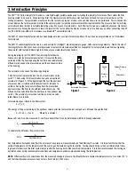
The 3M™ 101 Series Integrity Test Device is a small lightweight portable device used for testing the integrity of membrane filters within the filter
housing system to be used in. When testing a filter, the Operator only needs this document and does not need to know or remember any of the
testing parameters. Test parameters are entered into the test device program memory once and whenever a test is performed. The test device LED
screen displays the test pressure and instructs the operator when to close the pressure valve following stabilization. The pressure hold test will stop
automatically when the test is complete indicating a result by means of colored LEDs. Each filter test carried out is automatically saved into the test
device memory allowing the operator to recall the results of the test on either the display screen or to print a hard copy by either connecting the unit
to a PC with the mini-USB cord or wireless via a Bluetooth
TM
compatible printer.
The 3M 101 series integrity test device has been designed to test a variety of membrane filters. The unit can be programmed up to 19 individual
test protocols.
The 3M 101 series integrity test device is a semi-automatic “intelligent” precision pressure gauge, with a data storage memory. Due to the size of
the Integrity Tester, it does not have an integral valve for automatic pressure adjustment; consequently it is not completely autonomous, signaling
the operator with text and indicator lights to make a manual adjustment when needed.
During the integrity test, the 3M 101 series integrity test device
takes a very precise pressure measurement. It measures the pres-
sure drop within the housing during the test time and calculates the
diffusion rate based on the pressure drop and the upstream volume
of the housing.
The calculation is based on the following principles :
The filter system is pressurized on the up- stream side to a pres-
sure P1. The housing / filter combination has a known upstream
volume of V
1
(Figure 1). At the beginning of the test, the upstream
pressure source is isolated and the downstream P
1
left open to
ambient. During the test, gas will diffuse from the pressurized
upstream side of the filter to the ambient downstream side. This
diffusion will be calculated from the decrease in the upstream pres-
sure P
2
. The volume of gas lost due to diffusion V
2
can be calcu-
lated (Figure 2) as follows:
Total volume of gas initially in the filter system :
C = P
1
x V
1
The energy of the gas remaining in the upstream volume after the test plus the lost energy due to diffusion through the filter.
C = (P
2
x V
1
) + P
0
x V
2
Where P
0
is ambient
Because P
1
and P
2
can be measured, V
1
and P
0
are known then V
2
can be determined with the following calculation:
V
2
=
(P
1
- P
2
) x V
1
P
0
To calculate the diffusional flow rate mL/min:
Diff =
V
2
Test time (min)
Any temperature fluctuation will affect the accuracy of any pressure measurements and the diffusional flow rates. It is important that neither the
ambient temperature nor the temperature of the source gas fluctuate during the test period. Testing should not be carried out immediately follow-
ing steam sterilization of the filter system but only after the housing has cooled to ambient temperature. It is further recommended that testing be
performed under normal environmental conditions and temperature extremes are avoided during the testing period.
NOTE:
Diffusional flow rate calculations from the measured change in pressure, the Integrity Tester assumes the temperature is at a constant 20 °C
and that the atmospheric pressure does not vary from 14.5 psi (1000 mbar).
Volume
V
1
Pressure
on P
1
P
1
Pressurized Filter System
Volume
V
1
Pressure
on P
2
Ambient Pressure
P
0
Diffused Gas
P
0
* V
2
Figure 1
Figure 2


