background image

44

C

HAPTER

 4: M

AINTAINING

 S

OFTWARE

Using the BOOT


Menu

After you power on the Switch 8800, the BootROM program runs automatically. 
The terminal displays the following information: 

Starting...

        *************************************************

        *                                               *

        *        Switch 8800 Bootrom, Version 113       *

        *                                               *

        *************************************************

Copyright(C) 2000-2004 by 3COM Corporation, Inc.

      Creation date: Jul  5 2004, 10:43:58

      CPU type        : MPC755

      CPU L2 Cache    : 1024KB

      CPU Clock Speed : 400MHz

      BUS Clock Speed : 100MHz

      Memory Size     : 512MB

Flash file system init....done

Board self testing...........................

The board is steady

SlotNo of this board is 4

The MCX is existent

BootRom main system CRC check is OK

82559 register testing is OK

EPLD1 testing is OK

EPLD2 testing is OK

16c2552 register testing is OK

Please check LEDs......................LED testing finished

The switch's Mac address is 0040.9c30.b2d4

Press Ctrl+B to enter Boot Menu... 

The contents displayed on the terminal can vary with different versions of Boot 
ROM. 

If you press 

Ctrl+B

 immediately, the system displays the Boot Menu. If you do not 

press 

Ctrl+B

, the system initiates the program decompression process. At this time 

if you want to access the BOOT Menu, you must reboot the switch. 

1

Press 

Ctrl+B

. The system displays:

Initialize flash file system. Please wait!

Password :

Содержание 8800 SERIES

Страница 1: ...Switch 8800 Installation Guide Version 3 0 3C17500 14 slot Starter Kit 3C17501 10 slot Starter Kit 3C17502 7 slot Starter Kit and associated modules Part No 10014384 Document Number DUA1750 0AA01 Published December 2004 ...

Страница 2: ...ver is applicable You agree not to remove or deface any portion of any legend provided on any licensed program or documentation contained in or delivered to you in conjunction with this User Guide Unless otherwise indicated 3Com registered trademarks are registered in the United States and may or may not be registered in other countries 3Com and the 3Com logo are registered trademarks of 3Com Corp...

Страница 3: ... lists icon conventions that are used throughout this guide Table 2 lists text conventions that are used throughout this guide Table 1 Notice Icons Icon Notice Type Description Information note Information that describes important features or instructions Caution Information that alerts you to potential loss of data or potential damage to an application system or device Warning Information that al...

Страница 4: ...information in this guide differs from information in the release notes use the information in the Release Notes These documents are available in Adobe Acrobat Reader Portable Document Format PDF on the CD ROM that accompanies your router or on the 3Com World Wide Web site http www 3com com Words in italics Italics are used to Emphasize a point Denote a new term at the place where it is defined in...

Страница 5: ...ply is installed in the left power slot Switch Backplane The Switch 8800 backplane is part of the integrated chassis and delivers high speed data transfer between the Fabric and I O modules The backplane bandwidth capacity is 1 440 Tbps The backplane supports the following functions Interconnection of signals between modules Communication channels Hot swapping for modules Auto recognition of slots...

Страница 6: ...lowing fixed ports Compact Flash CF Port Management 10Base T 100Base TX port 1 Compact Flash port 7 I O module LEDs 2 Management 10BASE T 100BASE TX port 8 SFS LED 3 RS232 485 port 9 RUN LED 4 Console port 10 ALM LED 5 AUX modem port 11 ACT LED 6 Reset button Table 4 Fabric Specifications Item Specification Bandwidth 360 Gbps CPU MPC755 133 Mhz BootROM 512 KB SDRAM 512 KB Flash 16 MB Dimensions L ...

Страница 7: ...anagement 10Base T 100Base TX port RS232 RS485 port The RS232 RS485 port uses an RJ 45 connector to connect to an external power rack and monitor its status Table 7 lists specifications for the RS232 485 port Table 5 Management 10Base T 100Base TX Port Specifications Specification Description Port connector RJ 45 Number of ports 1 Port speed 10 Mbps half duple full duplex 100 Mbps half duplex full...

Страница 8: ...O modules as described in Table 10 Table 8 Console Port Specifications Specification Description Port connector RJ 45 Port standard Asynchronous EIA TIA 232 Baud rate 9600 bps by default Transmission distance 15 m 45 ft Services Connects with character terminal Connects with local or remote PC serial port and runs terminal emulation on a PC a pair of modems are required for a remote connection Tab...

Страница 9: ...with each installed I O module 1 Port 10GBASE X XENPAK Module The 1 port 10GBASE X XENPAK module provides a single 10 Gbps XENPAK port Figure 2 illustrates the front panel of the 1 port 10GBASE X XENPAK module Figure 2 Front Panel of the 1 Port 10GBASE X XENPAK Module 1 XENPAK port 2 XENPAK port LEDs Table 12 describes the 1 port 10GBASE X XENPAK module LEDs Table 11 Fabric Status LEDs LED Status ...

Страница 10: ...cification Description CPU MPC8245 BootROM 512 KB SDRAM 128 MB Dimensions L x W 366 7 x 340 mm 14 5 x 13 4 in Power consumption 60 W Connector SC Number of ports 1 Transmission rate 10 Gbps Transceiver cable and maximum transmission distance 3CXENPAK92 1310 nm single mode optical fiber 10 km 6 mi 3CXENPAK96 1310 nm single mode optical fiber 40 km 25 mi Table 12 1 Port 10GBASE X XENPAK Module LEDs ...

Страница 11: ...ts 2 Connector XFP LC Port transmission speed 10 Gbps Transceiver cable and maximum transmission distance 3CXFP92 1310 nm 9 125 µm single mode optical fiber 10 km 6 mi 3CXFP96 1550 nm 9 125 µm single mode optical fiber 40 km 25 mi Table 15 Specifications for the 2 Port 10GBASE X XFP Module continued Specification Description Table 16 12 Port 1000BASE X SFP Module LEDs LED Description LINK Off The ...

Страница 12: ... multi mode optical fiber 550 m 1804 ft 3CSFP92 1310 nm 9 125 µm single mode optical fiber 10 km 6 mi 3CSFP93 RJ 45 category 5 100 m 300 ft 3CSFP97 1550 nm 9 125 µm single mode optical fiber 70 km 43 mi Table 17 Specifications for the 12 Port 1000BASE X SFP Module continued Specification Description Table 18 24 Port 1000BASE X SFP Module LEDs LED Description LINK Off The port is not operating On T...

Страница 13: ...tical fiber 10 km 6 mi 3CSFP93 RJ 45 category 5 100 m 300 ft 3CSFP97 1550 nm 9 125 µm single mode optical fiber 70 km 43 mi Table 19 Specifications for the 24 Port 1000BASE X SFP Module continued Specification Description Table 20 24 Port 10 100 1000BASE T RJ45 Module LEDs LED Description LINK Off The port is not operating On The port is operating ACT Off No data is being transmitted Orange flashi...

Страница 14: ...7 illustrates the 1200 W power supply for the Switch 8800 Figure 7 Switch 8800 Power Supply Table 22 describes the power supply LEDs Table 23 describes the specifications of the power supply for the Switch 8800 chassis Table 22 Power Supply LED Status LED Description INPUT ON The power switch in the ON position and power input is normal OFF No power is being supplied OUTPUT ON Power output is norm...

Страница 15: ...l fans and is located on the right side of the chassis They operate on 48 V DC current Each starter kit includes the appropriate fan assembly Figure 8 illustrates the faceplate of the fan assembly for the 7 slot chassis Figure 8 Fan Assembly for the 7 Slot Chassis Table 25 describes the Status LEDs on the faceplate of the fan assembly Table 24 Switch 8800 Power Cords Power Cord Power Supply 7 slot...

Страница 16: ...plane through connectors Fan operation fault signals are collected and transmitted to the system alarm board through the backplane Table 26 Switch 8800 Fan Assembly Specification 7 Slot Chassis 10 Slot Chassis 14 Slot Chassis Fan assembly needed 1 3C17503 1 3C17504 2 3C17503 Number of fans 4 6 8 Power input 25 W 35 W 50 W ...

Страница 17: ...V to 264 V 47 to 63 Hz Max power consumption all components installed 665 W 975 W 1390 W Environment temperature and humidity 0 to 40 0 C 32 to 104 0 F and 5 to 85 Table 28 Switch 8800 Software Features Service Support Wire speed Layer 2 switching Switching capacity of 720 Gbps Packet forwarding rate at 428 Mpps Wire speed forwarding with forwarding delay less than 10µs for I O module ports Port a...

Страница 18: ...on source destination IP address and type of the upper layer protocol Plain text and MD5 text authentication for OSPF and RIP Version 2 DES56 Encryption for SNMP v3 Reliability VRRP QoS Traffic classification Bandwidth management based on port MAC address IP address TCP UDP port number ToS Diffserv value and CAR The granularity of bandwidth management is 64 Kbps Priority based on VLAN port IEEE 80...

Страница 19: ...ommendations Before installing your switch note the following safety recommendations Switch off the power supply before connecting the cables Keep the switch away from heat sources Do not keep the switch in a damp place and prevent liquid from getting into the switch Ensure that the neutral point of the power is grounded properly to avoid personal injury Ensure that the power is off before pluggin...

Страница 20: ...ld the power handles when carrying the switch Do not put fingers into the vent of the chassis when carrying the switch Since the power handles and vent have not been designed to bear the weight of the entire chassis using them to carry the switch may damage the switch or even injure personnel Laser Safety Some I O modules on the Switch 8800 have optical ports Make sure that an optical connector is...

Страница 21: ...ghtning damage do the following Install a lightning arrester on the input end of a telephone cable or other external line Ensure that the PGND wire of the chassis is well grounded Ensure that the neutral point of the socket of AC power supply is well grounded Install a lightning arrester at the input end of the power supply Installation Space For better heat dissipation and equipment maintenance 3...

Страница 22: ...ion screw and floating nuts that are shipped with the switch Installing on a Workbench To install the switch on a workbench take the following precautions Ensure that the workbench is smooth and stable Leave a heat dissipation clearance in the front and back of the switch of more than 1 m 3 ft and at least 0 8 meters 2 5 ft away from the walls on the sides Do not put heavy objects on the switch In...

Страница 23: ...a rack 3Com recommends that the ground wire of the switch be connected to the grounding bar of the rack WARNING The resistance between switch chassis and the ground should be less than 1 ohm Connecting and Configuring Power The Switch 8800 power supply has one power cord Use the procedures in the following sections to connect and configure power to your Switch 8800 Connecting AC Power Cords To con...

Страница 24: ... guides in the chassis and slide it gently into the slot 5 Push the fan until its positioning pin touches the hole in the chassis 6 Push the ejector levers inward 7 Push the handle bar pin into the hole in the chassis WARNING To avoid injury do not touch any naked wire terminal or any other part of the product labelled Dangerous Voltage Always wear the antistatic wrist strap when installing the fa...

Страница 25: ... of the AUX cable into the switch AUX port 2 Connect the DB 25 or DB 9 end of the AUX cable to the serial port of the virtual modem Connecting Module Cables This section describes how to connect electrical and optical cables Connecting Electrical Port Cables The 24 port 10 100 1000BASE T module require a RJ 45 connector and category 5 twisted pair cable See RJ 45 Connector on page 56 for an illust...

Страница 26: ...raised floor Collect all the transit data signal cable connectors and locate them on the floor of the chassis Power cords run out of the rear left of the chassis and on a cable rack or under a raised floor Cable Binding Keep the following precautions in mind as you bind cables Do not allow cables to twist or bend as you bind them The cable body cannot be bent at an angle that is more than twice it...

Страница 27: ...ve turned off the power before checking your installation Improper connections can injure people or damage components of the switch Table 30 Cable Binding Parameters Cable Bundle Diameter Space Between Bundles 10 mm 0 5in 80 150 mm 3 5 6 in 10 30 mm 5 1 2 in 150 200 mm 6 8 in 30 mm 1 2 in 200 300 mm 8 12 in Table 31 Installation Checklist Item Normal Abnormal Remarks Antistatic wrist strap Console...

Страница 28: ...28 CHAPTER 2 INSTALLING THE SWITCH 8800 ...

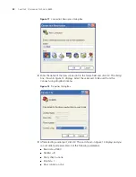
Страница 29: ...nnected to the switch console port using a console cable Figure 10 Connecting the Switch 8800 to a PC 1 Plug the DB 9 or DB 25 female plug of the console cable into the serial port of the PC or the terminal where the switch will be configured 2 Connect the RJ 45 connector of the console cable to the console port of the switch Setting Terminal Parameters To set terminal parameters and open a HyperT...

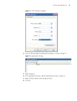
Страница 30: ... dialog box shown in Figure 12 displays Select the serial port to be used from the Connect using dropdown menu Figure 12 Properties Dialog Box 3 After selecting a serial port click OK The port shown in Figure 13 displays and you can set serial port parameters Set the following parameters Baud rate 9600 Databit 8 Parity check none Stopbit 1 Flow control none ...

Страница 31: ...log Box 4 Click OK The HyperTerminal dialogue box displays as shown in Figure 14 Figure 14 HyperTerminal Window 5 Select Properties 6 In the Properties dialog box select the Settings tab shown in Figure 15 7 Select VT100 in the Emulation dropdown menu 8 Click OK ...

Страница 32: ...00 verify that The Fabric and all I O modules have been properly installed Power cords have been properly connected The voltage of power supply can meet the requirements on the switch The console cable has been connected properly The PC or terminal for configuration has been started The terminal parameters have been set ...

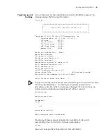
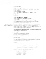
Страница 33: ...K EPLD1 testing is OK EPLD2 testing is OK 16c2552 register testing is OK Please check LEDs LED testing finished The switch s Mac address is 0040 9c30 b2d4 Press Ctrl B to enter Boot Menu 5 To enter Boot Mode see Chapter 6 press Ctrl B during the 5 seconds that Press Ctrl B to enter Boot Menu 5 is displayed To perform decompression immediately press ESC while this message is displayed If you do not...

Страница 34: ...34 CHAPTER 3 CONFIGURING THE SWITCH 8800 ...

Страница 35: ...re with FTP 1 Log in to the system with super user privileges 2 From the SW8800 command line transfer the file from the FTP server to the system using the ftp command 3 Specify the file to boot the system from using the boot command 4 Reboot the system using the reboot command The following example illustrates this procedure SW8800 su Password Now user privilege is 3 level and just commands which ...

Страница 36: ...work connection between the Ethernet port on the Switch 8800 Fabric module and the FTP TFTP server In addition you should verify that the file you want to use for the upgrade procedure is on the FTP TFTP server in the appropriate directory There are several procedures you must perform to complete this operation They are described in the following sections 1 Boot the System 2 Modify the Ethernet In...

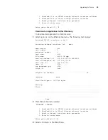
Страница 37: ...nter Boot Menu displays After five seconds the system begins program decompression If you want to access the BOOT Menu after this you must reboot the switch 1 Press Ctrl B The system displays Initialize flash file system Please wait Password CAUTION While using the switch keep in mind the modified BOOTROM password 2 Enter the BootROM password After entering the correct password no password is set ...

Страница 38: ...to previous field D quit boot device fei0 processor number 0 host name 8512 file name 88002 app 88003 app inet on ethernet e 192 168 25 210 inet on backplane b 192 168 25 158 host inet h 192 168 25 2 gateway inet g user u 1234 ftp password pw blank use rsh 1234 flags f 0x80 target name tn startup script s other o 3 Modify this information as follows file name Enter the name of the file you want to...

Страница 39: ... interface lo0 done boot device fei unit number 0 processor number 0 host name 8512 file name 88003 04 app inet on ethernet e 192 168 25 210 ffffff00 inet on backplane b 192 168 25 158 host inet h 192 168 25 2 user u 1234 ftp password pw 1234 flags f 0x80 Prepare for loading OK Loading done Free flash Space 9657344 bytes Writing Flash Done 2 The Ethernet Submenu displays ETHERNET SUBMENU 1 Downloa...

Страница 40: ...s After passing the negotiation the sending program begins to send the packet The receiving program checks the packet according to the negotiated means after receiving a complete packet The acknowledgement characters are sent after passing the check and then the sending program continues to send the next packet If the check fails negative characters are sent and the sending program sends the packe...

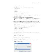
Страница 41: ...ch 8800 you must change the baud rate at the configuration terminal so that the two baud rates are the same When the baud rates are the same the Serial Submenu displays SERIAL SUBMENU 1 Download file to SDRAM through serial interface and boot 2 Download file to Flash through serial interface 3 Modify serial interface boot parameter 0 Return to main menu Enter your choice 0 3 2 7 Select option 2 an...

Страница 42: ...nterface and boot 2 Download file to Flash through serial interface 3 Modify serial interface boot parameter 0 Return to main menu Enter your choice 0 3 0 13 Select option 0 to return to the Main Menu MAIN MENU 1 Boot with default mode 2 Boot from Flash 3 Boot from CF card 4 Enter serial submenu 5 Enter ethernet submenu 6 Modify Flash description area 7 Modify bootrom password 0 Reboot Enter your ...

Страница 43: ...o the manufacturer s instructions and that it is enabled and pointing to the correct directory To upgrade using TFTP 1 Verify that you are logged in with super user privileges 2 From the Switch 8800 command line in user view TFTP the image file from the TFTP server to the Switch 8800 using the following command tftp TFTP Server IP Address get Source File image Dest File Optional 3 Set the boot par...

Страница 44: ...his board is 4 The MCX is existent BootRom main system CRC check is OK 82559 register testing is OK EPLD1 testing is OK EPLD2 testing is OK 16c2552 register testing is OK Please check LEDs LED testing finished The switch s Mac address is 0040 9c30 b2d4 Press Ctrl B to enter Boot Menu The contents displayed on the terminal can vary with different versions of Boot ROM If you press Ctrl B immediately...

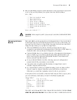
Страница 45: ...onfiguration information The Switch 8800 does not synchronize versions of the application file between Fabrics Therefore you must manually download the application file to one Fabric then copy the application file between Flashes to insure that both Fabrics can boot from the same file To insure that both Fabrics boot the same way you must configure boot parameters with the same values on each Fabr...

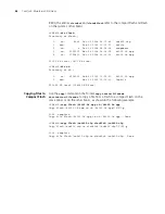
Страница 46: ...eb 10 2003 11 35 10 88003 01 app 1 drw Mar 16 2003 12 16 00 logfile 250352 KB total 234680 KB free Copying Files to Compact Flash Use the copy command in the format copy source filename destination filename to copy a file from a Flash to a compact Flash on the same Fabric or on the other Fabric as shown in the following example SW8800 copy flash 88003 04 app cf 88003 04 app Copy flash 88003 04 app...

Страница 47: ...the power cord 3 Loosen the captive screws on both sides of the power supply 4 Support the power supply with one hand and gently pull the handle with the other hand until it slides out of the slot 5 If you are not going to install another power supply in this slot install a blanking plate on the chassis for dust proofing and heat dissipation 6 Remove the new power supply from the package and verif...

Страница 48: ...ent or severe electrical shock Replacing I O Modules To replace an I O module you need An antistatic wrist strap A screwdriver To remove a module 1 Remove all the cables from the module to be removed 2 Loosen the captive screws 3 Hold the ejector levers on the module with both hands and press them toward both sides to separate the connectors of the module from the motherboard 4 Gently slide the mo...

Страница 49: ...th both hands pull out the ejector levers on the fan assembly to separate the fan assembly connector from the backplane 3 Pull the fan gently along the guides of the slot to remove it 4 With both hands pull out the ejector levers of the fan that will be installed Align it with the guides in the chassis and slide it gently into the slot until you feel the positioning pin on the handle bar touch the...

Страница 50: ...50 CHAPTER 5 MAINTAINING HARDWARE ...

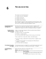
Страница 51: ...terminal after the Switch 8800 is powered on check that The power system is working normally The Fabric is working normally The console cable has been connected to the console port on the Fabric If this procedure does not reveal the problem verify the following The console cable is connected to the serial port that is configured on the terminal Console terminal parameters are set properly See Sett...

Страница 52: ...ower switch is in the ON position The power supply is installed right side up The FAIL LED is on Verify the following The correct power voltage is in use 90 to 264 V AC 50 to 60 Hz The air filter protecting the fan frame is clean If dust has accumulated on the air filter will block the fan frame from free ventilation and even lead to power supply failure If you cannot resolve an issue with the pow...

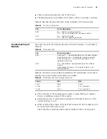
Страница 53: ... resetting the module if the ALM LED remains off the module may not be connected to the power source Check that the module has been properly installed in the correct position Table 33 Fan LEDs on the Fabric LED Status Description RUN On The fan is working normally Off The fan has failed or has not been installed ALM On The fan has failed Off The fan is operating normally Table 34 I O Module LEDs L...

Страница 54: ...54 CHAPTER 6 TROUBLESHOOTING ...

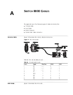
Страница 55: ...tors Figure 18 The Console cable Table 36 lists console cable pin outs AUX Cable Figure 19 illustrates the AUX cable Table 36 Console Cable Pin outs RJ 45 Signal Direction DB 25 DB 9 1 RTS 4 7 2 DTR 20 4 3 TXD 2 3 4 CD 8 1 5 GND 7 5 6 RXD 3 2 7 DSR 6 6 8 CTS 5 8 Enlarged A side Enlarged A side DB25 Female DB25 Female 8P8C Plug 8P8C Plug Enlarged B side Enlarged B side DB9 Female DB9 Female Enlarge...

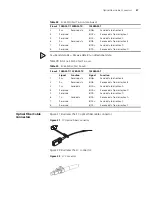
Страница 56: ...tion DB 25 DB 9 1 RTS 4 7 2 DTR 20 4 3 TXD 2 3 4 CD 8 1 5 GND 7 5 6 RXD 3 2 7 DSR 6 6 8 CTS 5 8 Enlarged B side Enlarged B side Enlarged A side Enlarged A side Enlarged C side Enlarged C side DB25 Male DB25 Male Label Label DB9Male DB9Male 8P8C Plug 8P8C Plug Table 38 RJ 45 MDI Port Pin outs Pinout 10BASE T 100BASE TX 1000BASE T Signal Function Signal Function 1 Tx Send data BIDA Send data to dire...

Страница 57: ... Receive data from direction B 7 Reserved BIDD Send data to direction D 8 Reserved BIDD Receive data from direction D Table 39 RJ 45 MDI X Port Pinouts Pinout 10BASE T 100 BASE TX 1000BASE T Signal Function Signal Function 1 Rx Receive data BIDB Send data to direction B 2 Rx Receive data BIDB Receive data from direction B 3 Tx Send data BIDA Send data to direction A 4 Reserved BIDD Receive data fr...

Страница 58: ...58 APPENDIX A SWITCH 8800 CABLES ...

Страница 59: ...on 3Com Extended Warranty and Professional Services is available at http www 3com com Contact your authorized 3Com reseller or 3Com for additional product and support information Troubleshoot Online You will find support tools posted on the 3Com web site at http www 3com com 3Com Knowledgebase helps you troubleshoot 3Com products This query based interactive tool is located at http knowledgebase 3...

Страница 60: ...oduct directly to 3Com for repair you must first obtain a return authorization number RMA Products sent to 3Com without authorization numbers clearly marked on the outside of the package will be returned to the sender unopened at the sender s expense If your product is registered and under warranty you can obtain an RMA number online at http eSupport 3com com First time users will need to apply fo...

Страница 61: ...ao Ecuador Dominican Republic 1 800 988 2112 0 810 444 3COM 1 800 998 2112 1 800 998 2112 1 800 998 2112 52 5 201 0010 1 800 998 2112 1 800 998 2112 0800 13 3COM 1 800 998 2112 AT T 800 998 2112 AT T 800 998 2112 AT T 800 998 2112 1 800 998 2112 AT T 800 998 2112 AT T 800 998 2112 Guatemala Haiti Honduras Jamaica Martinique Mexico Nicaragua Panama Paraguay Peru Puerto Rico Salvador Trinidad and To...

Страница 62: ...62 APPENDIX B OBTAINING SUPPORT FOR YOUR SWITCH 8800 ...

Отзывы: