background image

192

C

HAPTER

 11: 802.1X C

ONFIGURATION

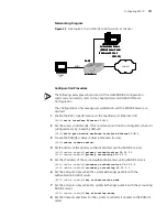
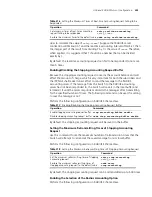
[4500-radius-radius1]

timer 5

[4500-radius-radius1]

retry 5

9

Set the interval for the system to transmit real-time accounting packets to the 
RADIUS server. 

[4500-radius-radius1]

timer realtime-accounting 15

10

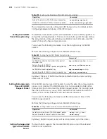
Configure the system to transmit the user name to the RADIUS server after 
removing the domain name. 

[4500-radius-radius1]

user-name-format without-domain

[4500-radius-radius1]

quit

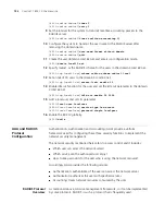
11

Create the user domain 3com163.net and enters isp configuration mode. 

[4500]

domain 3com163.net

12

Specify radius1 as the RADIUS scheme for the users in the domain 3com163.net. 

[4500-isp-3com163.net]

scheme radius-scheme radius1 local

13

Set a limit of 30 users to the domain 3com163.net. 

[4500-isp-3com163.net]

access-limit enable 30

14

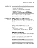
Enable idle cut function for the user and set the idle cut parameter in the domain 
3com163.net.

[4500-isp-3com163.net]

idle-cut enable 20 2000

15

Add a local user and sets its parameter.

[4500]

local-user localuser

[4500-luser-localuser]

service-type lan-access

[4500-luser-localuser]

password simple localpass

16

Enable the 802.1X globally. 

[4500]

dot1x

AAA and RADIUS 
Protocol 
Configuration

Authentication, Authorization and Accounting (AAA) provide a uniform 
framework used for configuring these three security functions to implement the 
network security management. 

The network security mentioned here refers to access control and it includes:

Which user can access the network server?

Which service can the authorized user enjoy? 

How to keep accounts for the user who is using the network resource? 

Accordingly, AAA provides the following services: 

Authentication: authenticates if the user can access the network server. 

Authorization: authorizes the user with specified services. 

Accounting: traces network resources consumed by the user. 

RADIUS Protocol

Overview

As mentioned above, AAA is a management framework, so it can be implemented 
by some protocols. RADIUS is such a protocol that is frequently used.

Содержание 400 Family

Страница 1: ...3Com Switch 4500 Family Configuration Guide http www 3Com com Part number 10015003 Published March 2006 ...

Страница 2: ...am or documentation contained in or delivered to you in conjunction with this User Guide Unless otherwise indicated 3Com registered trademarks are registered in the United States and may or may not be registered in other countries 3Com and the 3Com logo are registered trademarks of 3Com Corporation Cisco is a registered trademark of Cisco Systems Inc Funk RADIUS is a registered trademark of Funk S...

Страница 3: ...t Through a Dial up Modem 21 Command Line Interface 24 Command Line View 24 Features and Functions of Command Line 28 User Interface Configuration 30 User Interface Overview 30 User Interface Configuration 31 Displaying and Debugging User Interface 37 2 PORT OPERATION Ethernet Port Configuration 39 Ethernet Port Overview 39 Ethernet Port Configuration 39 Displaying and Debugging Ethernet Port 45 E...

Страница 4: ...y 69 Setting the PoE Mode on a Port 70 Enabling Disabling PD Compatibility Detect 70 Upgrading the PSE Processing Software Online 71 Displaying PoE Information 71 Configuration Example 71 5 NETWORK PROTOCOL OPERATION IP Address Configuration 73 IP Address Overview 73 Configuring IP Address 75 Displaying and Debugging IP Address 76 IP Address Configuration Example 77 Troubleshooting IP Address Conf...

Страница 5: ... Management Policy 99 Static Routes 100 Configuring Static Routes 101 Example Typical Static Route Configuration 103 Troubleshooting Static Routes 104 RIP 104 Configuring RIP 105 Displaying and Debugging RIP 113 Example Typical RIP Configuration 114 Troubleshooting RIP 115 IP Routing Policy 115 Configuring an IP Routing Policy 116 Displaying and Debugging the Routing Policy 119 Typical IP Routing ...

Страница 6: ...ion 143 Displaying and Debugging QoS Configuration 144 QoS Configuration Example 144 Port Mirroring Configuration Example 145 ACL Control Configuration 146 TELNET SSH User ACL Configuration 146 ACL Control Over Users Accessing Switches by SNMP 150 Configuring ACL Control for HTTP Users 152 9 STACKING Introduction to Stacking 155 Configuring a Stack 155 Specifying the Stacking VLAN of the Switch 15...

Страница 7: ...ity of a Specified Port 177 Configure a Specified Port to be Connected to Point to Point Link 177 Set mCheck of the Specified Port 178 Configure the Switch Security Function 178 Display and Debug RSTP 179 RSTP Configuration Example 180 11 802 1X CONFIGURATION IEEE 802 1X Overview 183 802 1X System Architecture 183 802 1X Authentication Process 184 Implementing 802 1X on the Switch 185 Configuring ...

Страница 8: ... State 205 Setting the Username Format Transmitted to the RADIUS Server 205 Setting the Unit of Data Flow that Transmitted to the RADIUS Server 206 Configuring the Local RADIUS Authentication Server 206 Configuring Source Address for RADIUS Packets Sent by NAS 207 Setting the Timers of the RADIUS Server 207 Displaying and Debugging AAA and RADIUS Protocol 208 AAA and RADIUS Protocol Configuration ...

Страница 9: ...m Debugging 237 Testing Tools for Network Connection 239 ping 239 Logging Function 240 Introduction to Info center 240 Info Center Configuration 244 Sending the Information to Loghost 247 Sending the Information to Control Terminal 248 Sending the Information to Telnet Terminal or Dumb Terminal 250 Sending the Information to the Log Buffer 252 Sending the Information to the Trap Buffer 253 Sending...

Страница 10: ...ONS Introduction to Password Control Configuration 287 Password Control Configuration 289 Configuration Prerequisites 289 Configuration Tasks 289 Configuring Password Aging 290 Configuring the Minimum Password Length 291 Configuring History Password Recording 291 Configuring User Login Password in Encryption Mode 292 Configuring Login Attempts Limitation and Failure Procession Mode 292 Configuring...

Страница 11: ...S Client 330 Windows 2000 Built in Client 331 Windows XP Built in Client 331 Aegis Client Installation 331 C AUTHENTICATING THE SWITCH 4500 WITH CISCO SECURE ACS Cisco Secure ACS TACACS and the 3Com Switch 4500 335 Setting Up the Cisco Secure ACS TACACS Server 335 Adding a 3Com Switch 4500 as a RADIUS Client 336 Adding a User for Network Login 338 Adding a User for Switch Login 339 ...

Страница 12: ......

Страница 13: ...thernet configuration Network Protocol Operation Details how to configure network protocols IP Routing Protocol Operation Details how to configure routing protocols Multicast Protocol Details how to configure multicast protocols ACL Configuration Details how to configure QoS ACL Stacking Configuration Details how to configure stacking RSTP Configuration Details how to configure RSTP 802 1X Configu...

Страница 14: ...es the variable part of a command text You must type a value here and press Return or Enter when you are ready to enter the command Example in the command super level a value in the range 0 to 3 must be entered in the position indicated by level x y Alternative items one of which must be entered are grouped in braces and separated by vertical bars You must select and enter one of the items Example...

Страница 15: ...13 Related Documentation The 3Com Switch 4500 Getting Started Guide provides information about installation The 3Com Switch 4500 Command Reference Guide provides all the information you need to use the configuration commands ...

Страница 16: ...14 ABOUT THIS GUIDE ...

Страница 17: ...etropolitan area network enterprise campus networking Multicast service multicast routing and audio and video multicast service Table 3 Models in the Switch 4500 family Model Power Supply Unit PSU Number of Service Ports Number of 10 100 Mbps Ports Number of 10 100 1000 Mbps Ports Number of 1000 Mbps SFP Uplink Ports Number of 1000 Mbps SFP Ports Console Port SW4500 26 AC input 26 24 2 2 1 SW4500 ...

Страница 18: ...e Switch 4500 stacking makes use of existing Gigabit connections for interconnecting the members of the stack Figure 1 Stacking Networking Topology Product Features Table 4 lists the function features Table 4 Function Features Features Description VLAN VLAN compliant with IEEE 802 1Q Standard Port based VLAN STP protocol Spanning Tree Protocol STP Rapid Spanning Tree Protocol RSTP compliant with I...

Страница 19: ...r management and password protect 802 1X authentication Packet filtering Quality of Service QoS Traffic classification Bandwidth control Priority Queues of different priority on the port Management and Maintenance Command line interface configuration Configuration through console port Remote configuration through Telnet or SSH Configuration through dialing the Modem SNMP Level alarms Output of deb...

Страница 20: ...18 CHAPTER 1 GETTING STARTED Databit 8 Parity check none Stopbit 1 Flow control none Terminal type VT100 Figure 3 Setting up a New Connection Figure 4 Configuring the Port for Connection ...

Страница 21: ...e port using the ip address command in VLAN Interface View and added the port that connects to a terminal to this VLAN using the port command in VLAN View you can Telnet this Switch and configure it 1 Authenticate the Telnet user through the console port before the user logs in by Telnet By default the password is required for authenticating the Telnet user to log in to the Switch If a user logs i...

Страница 22: ...lnet do not modify the IP address of the Switch unnecessarily for the modification might end the Telnet connection By default when a Telnet user passes the password authentication to log on to the Switch the access level for commands will be Level 0 Telneting a Switch Through Another Switch After a user has logged into a Switch it is possible to configure another Switch through the Switch through ...

Страница 23: ...P address of the Telnet Server If it is the hostname use the ip host command to specify 4 Enter the preset login password and you will see the prompt such 4500 If the prompt All user interfaces are used please try later appears it indicates that too many users are connected to the Switch through Telnet In this case connect later 5 Use the corresponding commands to configure the Switch or view it r...

Страница 24: ...er AT V to verify the Modem settings The Modem configuration commands and outputs may be different according to different Modems For details refer to the User Guide of the Modem 3Com recommends that the transmission rate on the console port must lower than that of Modem otherwise packets may be lost 3 To set up the remote configuration environment connect the Modems to a PC or a terminal serial po...

Страница 25: ...5 Enter the preset login password on the remote terminal emulator and wait for the prompt 4500 Then you can configure and manage the Switch Enter to view online help For details of specific commands refer to the following chapters By default after login a modem user can access the commands at Level 0 ...

Страница 26: ...ommands are classified into four levels namely visit level monitoring level system level and management level Visit level Commands in this level include network diagnosis tools such as ping and tracert commands for the different language environments of the user interface language mode and the telnet command etc The saving of the configuration file is not allowed at this command level Monitoring l...

Страница 27: ...ferent command views are implemented according to different requirements They are related to one another For example after logging in to the Switch you will enter User View in which you can only use some basic functions such as displaying the running state and statistics information In User View enter system view to enter System View in which you can key in different configuration commands and ent...

Страница 28: ... vlan interface 1 in System View quit returns to System View return returns to User View Local User View Configure local user parameters 4500 luser user1 Enter local user user1 in System View quit returns to System View return returns to User View User Interface View Configure user interface parameters 4500 ui0 Enter user interface 0 in System View quit returns to System View return returns to Use...

Страница 29: ...ed ACL View Define the rule of user defined ACL 4500 acl user 5000 Enter acl number 5000 in System View quit returns to System View return returns to User View QoS profile View Define QoS profile 4500 qos profile h3c Enter qos profile h3c in System View quit returns to System View return returns to User View RADIUS Server Group View Configure radius parameters 4500 radius 1 Enter radius scheme 1 i...

Страница 30: ...r initials in the command will be listed 4500 display ver version 5 Enter the first letters of a keyword of a command and press Tab If no other keywords begin with these letters then this unique keyword will be displayed automatically 6 To switch to the Chinese display for the above information perform the language mode command Displaying Characteristics of the Command Line The command line interf...

Страница 31: ...istory command display history command Display history command by user inputting Retrieve the previous history command Up cursor key or Ctrl P Retrieve the previous history command if there is any Retrieve the next history command Down cursor key or Ctrl N Retrieve the next history command if there is any Table 8 Common Command Line Error Messages Error messages Causes Unrecognized command Cannot ...

Страница 32: ...port are the same port There is only the one type of AUX user interface The user interface is numbered by absolute number or relative number To number the user interface by absolute number The AUX user interface is the first interface user interface 0 The number ranges from 0 to 7 The VTY is numbered after the AUX user interface The absolute number of the first VTY is the AUX user interface number...

Страница 33: ...ce only View By default the user interface supports Telnet and SSH protocols If the Telnet protocol is specified to ensure a successful login through Telnet you must configure the password by default If SSH protocol is specified to ensure a successful login you must configure the local or remote authentication of username and password using the authentication mode scheme command The protocol inbou...

Страница 34: ...mand Configure the transmission speed on the AUX console port speed speed_value Restore the default transmission speed on the AUX console port undo speed Table 13 Configuring the Flow Control on the AUX Console Port Operation Command Configure the flow control on the AUX console port flow control hardware none software Restore the default flow control mode on the AUX console port undo flow control...

Страница 35: ...s Note the following points For security the undo shell command can only be used on the user interfaces other than AUX user interface You cannot use this command on the user interface through which you log in You will be asked to confirm before using undo shell on any legal user interface Configuring Idle timeout By default idle timeout is enabled and set to 10 minutes on all the user interfaces T...

Страница 36: ...cation method to deny the access of an unauthorized user Perform the following configuration in User Interface View By default terminal authentication is not required for users logged in through the console port whereas the password is required for authenticating the Modem and Telnet users when they log in 1 Perform local password authentication to the user interface Using authentication mode pass...

Страница 37: ...ocal user zbr 4500 luser zbr password simple 3Com 4500 luser zbr service type telnet 3 No authentication 4500 ui vty0 authentication mode none By default the password is required for authenticating Modem and Telnet users when they log in If the password has not been set when a user logs in he will see the prompt Login password has not been set If the authentication mode none command is used the Mo...

Страница 38: ...s of level 3 and lower Setting the Command Priority The following command is used for setting the priority of a specified command in a certain view The command levels include visit monitoring system and management which are identified with 0 through 3 respectively An administrator assigns authorities as per user requirements Perform the following configuration in System View Do not change the comm...

Страница 39: ...tion before you use the auto execute command command and save the configuration Telnet 10 110 100 1 after the user logs in through VTY0 automatically 4500 ui vty0 auto execute command telnet 10 110 100 1 When a user logs on through VTY 0 the system will run telnet 10 110 100 1 automatically Displaying and Debugging User Interface After the above configuration use the display command in any view to...

Страница 40: ...cation information of the user interface display users all Display the physical attributes and some configurations of the user interface display user interface type number number summary Table 29 Displaying and Debugging User Interface Operation Command ...

Страница 41: ...full duplex and auto auto negotiation and its speed can be set to 1000 1000Mbps and auto auto negotiation The configuration of these Ethernet ports is fundamentally the same and is described in the following sections Ethernet Port Configuration Ethernet port configuration is described in the following sections Entering Ethernet Port View Enabling Disabling an Ethernet Port Setting the Description ...

Страница 42: ...net Port To configure a port to send and receive data packets at the same time set it to full duplex To configure a port to either send or receive data packets set it to half duplex If the port has been set to auto negotiation mode the local and peer ports will automatically negotiate the duplex mode Perform the following configuration in Ethernet Port View Table 30 Entering Ethernet Port View Ope...

Страница 43: ...he Ethernet Port Ethernet ports support straight through and cross over network cables Use the following command to configure the cable type Perform the following configuration in Ethernet Port View By default the cable type is auto auto recognized That is the system can automatically recognize the type of cable connecting to the port Enabling Disabling Flow Control for the Ethernet Port After flo...

Страница 44: ...sed for connecting to both Switches and the user s computers The difference between a hybrid port and a trunk port is that a hybrid port allows the packets from multiple VLANs to be sent without tags but a trunk port only allows the packets from the default VLAN to be sent without tags Perform the following configuration in Ethernet Port View Table 36 Enabling Disabling Flow Control for an Etherne...

Страница 45: ...er than VLAN 1 The VLAN to which a hybrid port is added must already exist The one to which a trunk port is added cannot be VLAN 1 After adding an Ethernet port to specified VLANs the local port can forward packets of these VLANs Hybrid and trunk ports can be added to multiple VLANs thereby implementing the VLAN intercommunication between peers For a hybrid Configure the port as a hybrid port port...

Страница 46: ...or an Ethernet Port Use the following command to enable port loopback detection and set the detection interval for the external loopback condition of each port If there is a loopback port found the Switch will put it under control Other correlative configurations function only when port loopback detection is enabled in System View Perform the following configuration in the view listed in Table 42 ...

Страница 47: ...on group take the port with minimum ID as the source if the copy destination is an aggregation group make the configurations of all group member ports identical with that of the source Displaying and Debugging Ethernet Port After the above configuration enter the display command in any view to display the running of the Ethernet port configuration and to verify the effect of the configuration Ente...

Страница 48: ...k port Ethernet1 0 1 Configure the trunk port with a default VLAN ID so that When receiving packets without a VLAN Tag the port can forward them to the member ports belonging to the default VLAN When it is sending the packets with VLAN Tag and the packet VLAN ID is the default VLAN ID the trunk port will remove the packet VLAN Tag and forward the packet Table 43 Displaying and Debugging Ethernet P...

Страница 49: ...g Take the following steps 1 Use the display interface or display port command to check if the port is a trunk port or a hybrid port If it is neither configure it as a trunk port or a hybrid port 2 Configure the default VLAN ID Link Aggregation Configuration Overview Brief Introduction to Link Aggregation Link aggregation means aggregating several ports together to implement the outgoing incoming ...

Страница 50: ...ting which port into from a certain dynamic aggregation group The operation key is a configuration set generated by LACP based on port setting speed duplex mode basic configuration and management key When LACP is enabled the management key of a dynamic aggregation port is 0 by default but the management key of a static aggregation port consists with the aggregation group ID For a dynamic aggregati...

Страница 51: ...ow speed half duplex high speed half duplex low speed The system sets to inactive state the ports which connect to different peer devices from one that the active port with minimum port number connects to or the ports in different aggregation groups though they are connected to the same peer device The system sets to inactive state the ports which cannot aggregate with the active port with minimum...

Страница 52: ...priority then the selected or standby state is determined by the port priority of the system You can decide whether the port is selected or standby by setting system priority and port priority Load Sharing In terms of load balancing link aggregation may be load balancing aggregation and non load balancing aggregation In general the system only provides limited load balancing aggregation resources ...

Страница 53: ...uration in Ethernet Port View By default LACP is disabled at the port Note that You cannot enable LACP at a stack port mirrored port port with a static MAC address configured port with static ARP configured port with 802 1X enabled port in a manual aggregation group You can add a port with LACP enabled into a manual aggregation group but then the LACP will be disabled on it automatically Or you ca...

Страница 54: ...nge a dynamic or static LACP aggregation group to a manual one or a dynamic LACP aggregation group to a static one In the former case LACP shall be disabled at the member ports automatically while in the latter case LACP shall remain enabled Adding Deleting an Ethernet Port into from an Aggregation Group You can add delete ports into from a manual or static LACP aggregation group but member port a...

Страница 55: ... system ID is given priority Changing system priority may affect the priority levels of member ports and further their selected or standby state Perform the following configuration in System View By default system priority is 32768 Configuring Port Priority The LACP compares system IDs first and then port IDs if system IDs are the same in determining if the member ports are selected or standby por...

Страница 56: ...isplay summary information of all aggregation groups display link aggregation summary Display detailed information of a specific aggregation group display link aggregation verbose agg_id Display local system ID display lacp system id Display detailed link aggregation information at the port display link aggregation interface interface_type interface_number interface_name to interface_type interfac...

Страница 57: ... 4500 link aggregation group 1 mode static b Add Ethernet ports Ethernet1 0 1 to Ethernet1 0 3 into aggregation group 1 4500 interface ethernet1 0 1 4500 Ethernet1 0 1 port link aggregation group 1 4500 Ethernet1 0 1 interface ethernet1 0 2 4500 Ethernet1 0 2 port link aggregation group 1 4500 Ethernet1 0 2 interface ethernet1 0 3 4500 Ethernet1 0 3 port link aggregation group 1 3 Dynamic LACP agg...

Страница 58: ...56 CHAPTER 2 PORT OPERATION ...

Страница 59: ... VLANs Therefore VLAN configurations are very helpful in controlling network traffic saving device investment simplifying network management and improving security Configuring a VLAN VLAN configuration is described in the following sections Creating Deleting a VLAN Adding Ethernet Ports to a VLAN Setting Deleting a VLAN or VLAN Interface Description Character String Specifying Removing the VLAN In...

Страница 60: ...name for example Vlan interface1 Interface Specifying Removing the VLAN Interface Use the following command to specify remove the VLAN interface To implement the network layer function on a VLAN interface the VLAN interface must be configured with an IP address and a subnet mask Perform the following configurations in System View Delete the specified VLAN undo vlan vlan_id to vlan_id all Table 52 ...

Страница 61: ...terface is enabled Displaying and Debugging VLAN After the above configuration enter the display command in any view to display the running of the VLAN configuration and to verify the effect of the configuration VLAN Configuration Example One Networking Requirements Create VLAN2 and VLAN3 Add Ethernet1 0 1 and Ethernet1 0 2 to VLAN2 and add Ethernet1 0 3 and Ethernet1 0 4 to VLAN3 Remove the speci...

Страница 62: ...ng Requirements Configure an IP address on a VLAN interface Networking Diagram Figure 15 VLAN Configuration Example 2 Configuration Procedure 1 If the VLAN does not currently exist then create it This example uses VLAN ID 3 4500 vlan 3 4500 vlan3 quit 2 Enter the VLAN interface view 4500 interface vlan interface 3 3 Provide the IP address and subnet mask 4500 Vlan interface3 ip address 192 168 1 5...

Страница 63: ...iguration of Voice VLAN is described in the following sections Enabling Disabling Voice VLAN Features Enabling Disabling Voice VLAN Features on a Port Voice VLAN Mode Type of IP Phone Port Mode Auto mode Tagged IP Phone Access Not supported Trunk Supported but the default VLAN of the connected port must exist and cannot be the voice VLAN The default VLAN is allowed to pass the connected port Hybri...

Страница 64: ...Removing the OUI Address Learned by Voice VLAN Configure OUI addresses which can be learned by Voice VLAN using the following command otherwise the system uses the default OUI addresses as the standard of IP Phone traffic The OUI address system can learn 16 MAC addresses at most Adding the OUI addresses you need only input the first three byte values of the MAC address Perform the following config...

Страница 65: ... By default Voice VLAN auto mode is enabled Setting the Aging Time of Voice VLAN In auto mode using the follow command you can set the aging time of Voice VLAN After the OUI address the MAC address of IP Phone is aged on the port this port enters the aging phase of Voice VLAN If OUI address is not learned by a port within the aging time the port is automatically deleted from Voice VLAN This comman...

Страница 66: ...onfigure the port Ethernet1 0 2 as the IP Phone access port The type of IP Phone is untagged Network Diagram Figure 16 Voice VLAN Configuration Configuration Steps 4500 vlan 2 4500 vlan2 port ethernet1 0 2 4500 vlan2 interface ethernet1 0 2 4500 Ethernet1 0 2 voice vlan enable Table 64 Configuring the Aging Time of Voice VLAN Operation command Set the aging time of Voice VLAN voice vlan aging minu...

Страница 67: ...LAN Configuration 65 4500 Ethernet1 0 2 quit 4500 undo voice vlan mode auto 4500 voice vlan mac_address 0011 2200 0000 mask ffff ff00 0000 description private 4500 voice vlan 2 enable 4500 voice vlan aging 100 ...

Страница 68: ...66 CHAPTER 3 VLAN OPERATION ...

Страница 69: ...m 328 feet z Each Ethernet port can supply at most 15400 mW of power to a PD z When AC power input is adopted for the switch the maximum total power that can be provided by the PWR switches is 300 W These switches can determine whether to supply power to the next remote PD it detected depending on the total power z When DC power input is adopted for the switch the PWR switches are capable of suppl...

Страница 70: ... use the following command to enable disable the PoE feature on a port in accordance with the network requirement Perform the following configuration in Ethernet Port View Table 67 Enabling disabling PoE feature on a port By default the PoE feature of each port is enabled Table 66 PoE Configuration Device Configuration Default Description Switch 4500 26 Port PWR Switch 4500 50 Port PWR Enabling Di...

Страница 71: ...uto mode when the switch is reaching its full load in supplying power it will first supply power to the PDs that are connected to the ports with critical priority and then supply power to the PDs that are connected to the ports with high priority For example Port A has the priority of critical When the switch is reaching its full load and a new PD is now added to port A the switch will power down ...

Страница 72: ...th the 802 3af standard and then supply power to them You can use the following commands to enable disable the PD compatibility detect function Perform the following configuration in System View Table 72 Enabling Disabling the PD Compatibility Detect By default the PD compatibility detect function is disabled Operation Command Set the power supply management mode on the Switch to auto poe power ma...

Страница 73: ...ation of the PoE feature on the switch and verify the effect of the configuration Table 74 PoE Information Display For more information on the parameters refer to the Command Reference Guide Configuration Example Networking Requirements The Ethernet1 0 1 and Ethernet1 0 2 ports of the Switch 4500 PWR are connected with a PD and an access point AP respectively The Ethernet1 0 24 port is intended to...

Страница 74: ...e 4500 Ethernet1 0 2 poe enable 4500 Ethernet1 0 24 poe enable Set the maximum power output of Ethernet1 0 1 and Ethernet1 0 2 to 12000 and 3000 mW respectively 4500 Ethernet1 0 1 poe max power 12000 4500 Ethernet1 0 2 poe max power 3000 Set the priority of Ethernet1 0 24 to critical to guarantee the power feeding to the AP to which this port connects 4500 Ethernet1 0 24 poe priority critical Set ...

Страница 75: ...nternet It consists of two fields net id field and host id field There are five types of IP address See Figure 18 Figure 18 Five Classes of IP Address Class A Class B and Class C are unicast addresses while Class D addresses are multicast addresses and Class E addresses are reserved for special applications The first three types are commonly used 0 1 2 3 4 5 6 7 8 9 10 11 12 13 14 15 16 17 18 19 2...

Страница 76: ...t is not put into use after starting up The IP address with network number as 0 indicates the current network and its network can be cited by the router without knowing its network number Network ID with the format of 127 X Y Z is reserved for self loop test and the packets sent to this address will not be output to the line The packets are processed internally and regarded as input packets B 128 ...

Страница 77: ...rface in one of three ways Using the IP address configuration command Allocated by BOOTP server Allocated by DHCP server These three methods are mutually exclusive and a new configuration will replace the current IP address For example if you apply for an IP address using the ip address bootp alloc command the address allocated by BOOTP shall replace the currently configured IP address This sectio...

Страница 78: ...llowing configuration in VLAN Interface View By default the IP address of a VLAN interface is null Displaying and Debugging IP Address After the above configuration enter the display command in any view to display the IP addresses configured on interfaces of the network device and to verify the effect of the configuration Table 76 Configuring the Host Name and the Corresponding IP Address Operatio...

Страница 79: ...re on the same network segment If the configuration is correct enable ARP debugging on the Switch and check whether the Switch can correctly send and receive ARP packets If it can only send but cannot receive ARP packets there are possibly errors occurring on the Ethernet physical layer ARP Configuration Introduction to ARP Necessity of ARP An IP address cannot be directly used for communication b...

Страница 80: ...st A The reply packet will be directly sent to Host A in stead of being broadcast Receiving the reply packet Host A will extract the IP address and the corresponding MAC address of Host B and add them to its own ARP mapping table Then Host A will send Host B all the packets standing in the queue Normally dynamic ARP automatically executes and searches for the resolution from the IP address to the ...

Страница 81: ...aging time of the dynamic ARP aging timer is 20 minutes Configuring the Creation of ARP Entries for Multicast Packets Use the following command to specify whether the Switch should create ARP table entries for multicast MAC addresses Address resolution for multicast packets is not required because the IANA Internet Assigned Numbers Authority have reserved a block of Ethernet addresses that map on ...

Страница 82: ...he DHCP relay serves as conduit between the DHCP Client and the server located on different subnets The DHCP packets can be relayed to the destination DHCP server or Client across network segments The DHCP clients on different networks can use the same DHCP server This is economical and convenient for centralized management A typical DHCP application often contains a DHCP server and several client...

Страница 83: ...ient the client only accepts the first received one and then broadcasts DHCP_Request messages respectively to those DHCP servers The message contains the information of the IP address request from the selected DHCP server Acknowledge stage the stage when the DHCP server acknowledges the IP address When receiving the DHCP_Request message from the client the DHCP server sends the DHCP_ACK message co...

Страница 84: ... above applies only when DHCP clients and server s are in the same subnet and it does not support trans segment networking To achieve dynamic address configuration you would have to configure a DHCP server for each subnet which is not a practical solution Introduction of DHCP relay has solved this problem the clients in a LAN can communicate with DHCP servers in another subnet through DHCP relay t...

Страница 85: ...ing sections Configuring the IP address for the DHCP server Configuring the DHCP Server Group for the VLAN Interfaces Configuring the IP address for the DHCP server You can configure a master and a backup DHCP server which are in the same DHCP server group in the same network segment to ensure reliability Perform the following configuration in System View By default no IP address is configured for...

Страница 86: ...le 85 Configuring the DHCP Server Group Corresponding to VLAN Interfaces Operation Command Configure DHCP server group corresponding to VLAN interfaces dhcp server groupNo Delete DHCP server group undo dhcp server Table 86 Displaying and Debugging DHCP Configuration Operation Command Display configuration information of DHCP server group display dhcp server groupNo Display configuration informatio...

Страница 87: ...rver 0 4500 Vlan interface1 quit 4500 interface vlan interface 10 4500 Vlan interface10 dhcp server 0 4500 Vlan interface10 quit DHCP Relay Configuration Example Two Networking Requirements The segment address for the DHCP Client is 10 110 0 0 which is connected to a port in VLAN2 on the Switch The IP address of the DHCP Server is 202 38 1 2 The DHCP packets should be forwarded via the Switch with...

Страница 88: ...figured 2 Use the display vlan and display ip interface vlan interface commands to check if the VLAN and the corresponding interface IP address have been configured 3 Ping the configured DHCP Server to ensure that the link is connected 4 Ping the IP address of the VLAN interface of the Switch to which the DHCP user is connected from the DHCP Server to make sure that the DHCP Server can correctly f...

Страница 89: ...IP Address Pool Based on the Port Configuring Layer 2 Isolation Between Ports Enabling Disabling Access Management Trap Enabling Disabling Access Management You can use the following command to enable the access management function Only after the access management function is enabled will the access management features IP and port binding and Layer 2 port isolation take effect Perform the followin...

Страница 90: ...on the same unit within an aggregation group Note the following When a port in an aggregation group is added to or removed from an isolation group then all the other ports of this aggregation group on the same unit are automatically added in or removed from this isolation group In the same aggregation group the port isolation feature on one unit is consistent If a port is removed from an aggregati...

Страница 91: ... 1 is connected to port 1 of the Switch and organization 2 to port 2 Ports 1 and 2 belong to the same VLAN The IP addresses range 202 10 20 1 to 202 10 20 20 can be accessed from port 1 and the range 202 10 20 21 to 202 10 20 50 from the port 2 Organization 1 and organization 2 cannot communicate with each other Networking Diagram Figure 25 Networking Diagram for Port Isolation Configuration Confi...

Страница 92: ...ng the CLI the following commands should be entered from System View 4500 system view 4500 acl number 2500 4500 acl basic 2500 rule 0 permit source 10 10 10 1 0 0 0 255 To delete this feature enter 4500 system view 4500 acl number 2500 4500 acl basic 2500 undo rule 0 UDP Helper Configuration Overview of UDP Helper The major function of the UDP Helper is to relay forward UDP broadcast packets that ...

Страница 93: ...e following configuration in System View Note that You must first enable the UDP Helper function and then configure the UDP port with the relay function Otherwise error information will appear The parameters dns netbios ds netbios ns tacacs tftp and time respectively refer to the six default ports You can configure the default UDP port in two ways specifying port IDs and specifying the correct par...

Страница 94: ...er the above configuration enter the display command in any view to display the running of the UDP Helper destination server and to verify the effect of the configuration Enter the debugging command in User View to debug UDP Helper configuration UDP Helper Configuration Example Networking Requirement The IP address of VLAN interface 2 on the Switch is 10 110 1 1 which is connected with network seg...

Страница 95: ...it timer If response packets are not received before synwait timeout the TCP connection will be terminated The timeout of synwait timer range is 2 to 600 seconds and it is 75 seconds by default finwait timer When the TCP connection state turns from FIN_WAIT_1 to FIN_WAIT_2 finwait timer will be started If FIN packets are not received before finwait timer timeout the TCP connection will be terminat...

Страница 96: ...Attributes Operation Command Table 98 Displaying and Debugging IP Performance Operation Command Display TCP connection state display tcp status Display TCP connection statistics data display tcp statistics Display UDP statistics information display udp statistics Display IP statistics information display ip statistics Display ICMP statistics information display icmp statistics Display socket inter...

Страница 97: ...Destination IP Address 202 38 160 1 Destination port 4296 Use the debugging tcp packet command to enable the TCP debugging to trace the TCP packets Operations include 4500 terminal debugging 4500 debugging tcp packet Then the TCP packets received or sent can be checked in real time Specific packet formats include TCP output packet Source IP address 202 38 160 1 Source port 1024 Destination IP Addr...

Страница 98: ...96 CHAPTER 5 NETWORK PROTOCOL OPERATION ...

Страница 99: ...two nodes and these two nodes are considered adjacent in the Internet Adjacent routers are two routers connected to the same network The number of route segments between a router and hosts in the same network is zero When the Switch 4500 runs a routing protocol it can perform router functions In this guide a router and its icon represent either a generic router or a Switch 4500 running routing pro...

Страница 100: ... segment where the destination host or router is located For example if the destination address is 129 102 8 10 the address of the network where the host or the router with the mask 255 255 0 0 is located is 129 102 0 0 The output interface Indicates an interface through which an IP packet should be forwarded The next hop address Indicates the next router that an IP packet will pass through The pr...

Страница 101: ...ute with the highest preference becomes the current route Routing protocols and the default preferences of the routes that they learn are shown in Table 99 The smaller the value the higher the preference Except for direct routing the preferences of various dynamic routing protocols can be manually configured to meet the user requirements The preferences for individual static routes can be differen...

Страница 102: ...r sends data via the main route When the line fails the main route will hide itself and the router will choose from one of the remaining routes as a backup route whose precedence is higher than the others to send data This process is the switchover from the main route to the backup route When the main route recovers the router will restore it by re selecting the main route As the main route has th...

Страница 103: ... entry of the routing table the router selects the default route to forward this packet If there is no default route and the destination address of the packet fails to match any entry in the routing table the packet is discarded and an Internet Control Message Protocol ICMP packet is sent to the originating host to indicate that the destination host or network is unreachable In a typical network t...

Страница 104: ... address of the local Switch as the next hop address of an static route Preference For different configurations of preference_value you can flexibly apply the routing management policy Other parameters The attributes reject and blackhole indicate the unreachable route and the blackhole route respectively Configuring a Default Route Perform the following configurations in System View The parameters...

Страница 105: ...d View routing table summary display ip routing table View routing table details display ip routing table verbose View the detailed information of a specific route display ip routing table ip_address mask longer match verbose View the route information in the specified address range display ip routing table ip_address1 mask1 ip_address2 mask2 verbose View the route filtered through specified basic...

Страница 106: ...rresponding route is valid RIP Routing Information Protocol RIP is a simple dynamic routing protocol that is Distance Vector D V algorithm based It uses hop counts to measure the distance to the destination host This is called the routing cost In RIP the hop count from a router to its directly connected network is 0 the hop count to a network which can be reached through another router is 1 and so...

Страница 107: ...ion about their local routing tables 2 After receiving the response packets the router that sent the request modifies its own routing table and sends a modification triggering packet to the neighbor router The neighbor router sends this packet to all its neighbor routers After a series of modification triggering processes each router can get and keep the updated routing information 3 RIP broadcast...

Страница 108: ...nal Routing Metrics Configuring Route Filtering Enabling RIP and Entering the RIP View Perform the following configurations in System View By default RIP is not enabled Enabling RIP on a Specified Network For flexible control of RIP operation you can specify the interface and configure the network on which the interface is located to the RIP network so that these interfaces can send and receive RI...

Страница 109: ...commands rip work rip output rip input and network Specifying the RIP Version RIP has two versions RIP 1 and RIP 2 You can specify the version of the RIP packet used by the interface RIP 1 broadcasts the packets RIP 2 can transmit packets by both broadcast and multicast By default multicast is adopted for transmitting packets In RIP 2 the default multicast address is 224 0 0 9 The advantage of tra...

Страница 110: ...t time of the garbage collection timer is not fixed If the period update timer is set to 30 seconds the garbage collection timer might range from 90 to 120 seconds Before RIP completely deletes an unreachable route from the routing table it advertises the route by sending four update packets with a route metric of 16 to let all the neighbors know that the route is unreachable Routes do not always ...

Страница 111: ...abling Host Route In some cases the router can receive many host routes from the same segment and these routes are of little help in route addressing but consume a lot of network resources Routers can be configured to reject host routes by using the undo host route command Perform the following configurations in RIP View By default the router receives the host route Table 109 Configuring Zero Fiel...

Страница 112: ...y is not encrypted and can be seen in a network trace so simple authentication should not be applied when there are high security requirements MD5 authentication This mode uses two packet formats One format follows RFC1723 and the other follows RFC2082 Perform the following configuration in Interface View The usual packet format follows RFC1723 and nonstandard follows RFC2082 Configuring Split Hor...

Страница 113: ...ommand to import the routes of other protocols you can specify their cost If you do not specify the cost of the imported route RIP will set the cost to the default cost specified by the default cost parameter Perform the following configurations in RIP View By default the cost value for the RIP imported route is 1 Table 114 Configuring Split Horizon Operation Command Enable split horizon rip split...

Страница 114: ...by the router and RIP routes generated by the router itself which means that it has no effect on the routes imported to RIP by other routing protocols Configuring Route Filtering The Router provides a route filtering function You can configure the filter policy rules by specifying the ACL and ip prefix for route redistribution and distribution To import a route the RIP packet of a specific router ...

Страница 115: ...o Filter the Received Routes Operation Command Filter the received routing information distributed by the specified address filter policy gateway ip_prefix_name import Cancel filtering of the received routing information distributed by the specified address undo filter policy gateway ip_prefix_name gateway ip prefix name route policy route policy name import Filter the received global routing info...

Страница 116: ...P addresses for the VLAN interfaces are configured 1 Configure RIP on Switch A Switch A rip Switch A rip network 110 11 2 0 Switch A rip network 155 10 1 0 2 Configure RIP on Switch B Switch B rip Switch B rip network 196 38 165 0 Switch B rip network 110 11 2 0 Enable the debugging of RIP receiving packet debugging rip receive Disable the debugging of RIP receiving packet undo debugging rip recei...

Страница 117: ...ifying the characteristics of the routing information to be filtered You can set the rules based on such attributes as the destination address and source address of the information The rules can be set in advance and then used in the routing policy to advertise receive and import the route information The Switch 4500 supports three kinds of filters The following sections introduce these filters Ro...

Страница 118: ...n and the domain of the routing information In addition in the IP Prefix you can specify the gateway options and require it to receive only the routing information distributed by some certain routers An IP Prefix is identified by the ip prefix name Each IP Prefix can include multiple list items and each list item can specify the match range of the network prefix forms and is identified with an ind...

Страница 119: ...routing policy denies the routing information If all the nodes in the route policy are in deny mode all routing information is denied by the route policy Defining If match Clauses for a Route policy The if match clauses define the matching rules that the routing information must satisfy to pass the route policy The matching objects are attributes of the routing information Perform the following co...

Страница 120: ...distribution If the destination routing protocol that imports the routes cannot directly reference the route costs of the source routing protocol you should satisfy the requirement of the destination protocol by specifying a route cost for the imported route In different routing protocol views the parameter options are different For details refer to the description of the import route command for ...

Страница 121: ...he routing policy configuration and to verify the effect of the configuration Typical IP Routing Policy Configuration Example Configuring the Filtering of the Received Routing Information Networking Requirements Switch A communicates with Switch B running RIP protocol Import three static routes by enabling the RIP protocol on Switch A The route filtering rules can be configured on Switch B to make...

Страница 122: ...ch A rip 1 area 0 0 0 0 network 10 0 0 0 0 255 255 255 d Import the static routes Switch A rip 1 import route static 2 Configure Switch B a Configure the IP address of VLAN interface Switch B interface vlan interface 100 Switch B Vlan interface100 ip address 10 0 0 2 255 0 0 0 b Configure the access control list Switch B acl number 2000 Switch B acl basic 2000 rule deny source 30 0 0 0 0 255 255 2...

Страница 123: ...Route Policy When all the nodes of the Route Policy are in the deny mode then all the routing information cannot pass the filtering of the Route Policy The if match mode of at least one list item of the ip prefix should be the permit mode The list items of the deny mode can be firstly defined to rapidly filter the routing information not satisfying the requirement but if all the items are in the d...

Страница 124: ...122 CHAPTER 6 IP ROUTING PROTOCOL OPERATION ...

Страница 125: ... IGMP host it will remove the host from the corresponding multicast table The switch continuously listens to the IGMP messages to create and maintain MAC multicast address table on Layer 2 And then it can forward the multicast packets transmitted from the upstream router according to the MAC multicast address table When IGMP Snooping is disabled the packets are multicast to all ports see Figure 32...

Страница 126: ...h 4500 Router port aging time Time set on the router port aging timer If the switch has not received any IGMP general query messages before the timer times out it is no longer considered a router port Multicast group member port aging time When a port joins an IP multicast group the aging timer of the port will begin timing If the switch has not received any IGMP report messages before the timer t...

Страница 127: ...member When a router port receives an IGMP general query message the Switch 4500 will reset the aging timer of the port When a port other than a router port receives the IGMP general query message the Switch 4500 will notify the multicast router that a port is ready to join a multicast group and starts the aging timer for the port Internet IGMP packets A Ethernet Switch running IGMP Snooping A rou...

Страница 128: ...ved the message to the group starts the port aging timer and then adds all the router ports in the native VLAN of the port into the MAC multicast forwarding table Meanwhile it creates an IP multicast group and adds the port received to it If the corresponding MAC multicast group exists but does not contain the port that received the report message the switch adds the port into the multicast group ...

Страница 129: ...to manually configure the maximum response time If the Switch 4500 receives no report message from a port within the maximum response time the switch will remove the port from the multicast group Perform the following configuration in System View By default the maximum response time is 10 seconds Configuring Aging Time of Multicast Group Member Use the commands in Table 132 to manually set the agi...

Страница 130: ...h first enable it The switch is connected to the router via the router port and with user PCs through the non router ports on vlan 10 Table 132 Configuring aging time of the multicast member Operation Command Configure aging time of the multicast member igmp snooping host aging time seconds Restore the default setting undo igmp snooping host aging time Table 133 Displaying and debugging IGMP Snoop...

Страница 131: ...switch disabled IGMP Snooping check whether the IGMP Snooping is enabled globally and also enabled on the VLAN If IGMP Snooping is not enabled globally first input the igmp snooping enable command in System View and then input the igmp snooping enable command in VLAN view If IGMP Snooping is not enabled on the VLAN input the igmp snooping enable command in VLAN view Diagnosis 2 Multicast forwardin...

Страница 132: ...mp snooping group to check if MAC multicast forwarding table in the bottom layer and that created by IGMP Snooping is consistent You may also input the display mac vlan command in any view to check if MAC multicast forwarding table under vlanid in the bottom layer and that created by IGMP Snooping is consistent 2 If they are not consistent refer to Technical Support for assistance ...

Страница 133: ...acket with the access control rule the issue of match order arises Filtering or Classifying Data Transmitted by the Hardware ACL can be used to filter or classify the data transmitted by the hardware of the Switch In this case the match order of the ACL s sub rules is determined by the Switch hardware The match order defined by the user will not be effective The case includes ACL cited by QoS func...

Страница 134: ... smaller range is listed ahead If the port numbers are in the same range follow the configuration sequence ACL Supported by the Switch The table below lists the limits to the numbers of different types of ACL on a Switch Table 134 Quantitative Limitation to the ACL Configuring ACL ACL configuration includes Defining ACL Activating ACL The above steps must be done in sequence Define the ACL using t...

Страница 135: ...UDP port number in use and packet priority to process the data packets The advanced ACL supports the analysis of three types of packet priorities ToS Type of Service IP and DSCP priorities You can use the following command to define advanced ACL Perform the following configuration in the corresponding view Table 136 Define Advanced ACL Operation Command Enter basic ACL view from System View acl nu...

Страница 136: ...to understand the Layer 2 data frame structure Any packet ending up at the FFP Fast Filter Processor that performs ACL functionality will contain a VLAN tag Even packets that ingress the Switch untagged will be tagged at the FFP You can use the following commands to define user defined ACL Perform the following configuration in corresponding view Delete a sub item from the ACL from Advanced ACL Vi...

Страница 137: ...mand in all views to display the running of the ACL configuration and to verify the effect of the configuration Execute reset command in User View to clear the statistics of the ACL module Table 140 Display and Debug ACL Operation Command Enter user defined ACL view from System View acl number acl_number match order config auto Add a sub item to the ACL from User defined ACL View rule rule_id perm...

Страница 138: ...ion Example Configuration Procedure In the following configurations only the commands related to ACL configurations are listed 1 Define the work time range Define time range from 8 00 to 18 00 4500 time range 3Com 8 00 to 18 00 working day 2 Define the ACL to access the payment server a Enter the numbered advanced ACL number as 3000 4500 acl number 3000 match order config b Define the rules for ot...

Страница 139: ...efine the time range Define time range from 8 00 to 18 00 4500 time range 3Com 8 00 to 18 00 daily 2 Define the ACL for packet which source IP is 10 1 1 1 a Enter the number basic ACL number as 2000 4500 acl number 2000 b Define the rules for packet which source IP is 10 1 1 1 4500 acl basic 2000 rule 1 deny source 10 1 1 1 0 time range 3Com 3 Activate ACL Activate the ACL 2000 4500 GigabitEtherne...

Страница 140: ... GigabitEthernet1 0 50 packet filter inbound link group 4000 QoS Configuration Traffic Traffic refers to all packets passing through a Switch Traffic Classification Traffic classification means identifying the packets with certain characteristics using the matching rule called classification rule set by the configuration administrator based on the actual requirements The rule can be very simple Fo...

Страница 141: ...can be used and defined in different QoS modules Queue Scheduling When congestion occurs several packets will compete for the resources The queue scheduling algorithm is used to overcome the problem Weighted Round Robin WRR Round scheduling ensures every queue is given some service time on the Switch port Take 4 egress queues for each port as an example WRR gives each queue a weight w3 w2 w1 and w...

Страница 142: ...d by a packet with the port priority Configuring Trust Packet Priority The system replaces the 802 1p priority carried by a packet with the port priority by default The user can configure system trusting the packet 802 1p priority and not replacing the 802 1p priorities carried by the packets with the port priority Perform the following configuration in Ethernet Port View Table 142 Configuring Por...

Страница 143: ...ernet Port View Table 144 Configure Mirroring Port Delete Port Mirroring 1 Delete mirroring port Perform the following configuration in the Ethernet Port View Table 145 Delete Mirroring Port 2 Delete monitor port Perform the following configuration in the Ethernet Port View Table 146 Delete Monitor Port Configuring Traffic Mirroring The function of traffic mirroring is to copy the traffic matching...

Страница 144: ...e Guide Configuring the Mapping Relationship Between COS and Local Precedence The default mapping relationship between 802 1p priority and output queue of the port is as follows Table 151 Mapping between 802 1p Priority Levels and Outbound Queues Perform the following configuration in System View Operation Command Configure traffic mirroring mirrored to inbound outbound user group acl_number rule ...

Страница 145: ... to rate limit based on the port that is limiting the total rate at the port The granularity of line rate is 64 kbps Perform the following configurations in the Ethernet Port View Table 154 Setting Line Rate Configuring WRED Operation The function of WRED Operation is to avoid congestion in advance Operation Command Configure COS Local precedence map qos cos local precedence map cos0_map_local_pre...

Страница 146: ...ority level 4 Operation Command Configure WRED Operation wred queue_index qstart probability Cancel the configuration of WRED Operation undo wred queue_index Operation Command Display mirroring configuration display mirror Display queue scheduling mode display queue scheduler Display line rate for outbound packets display qos interface interface_name interface_type interface_num unit_id line rate ...

Страница 147: ...the wage server a Limit average traffic from the wage server at 128 Kbps and label over threshold packets with priority level 4 4500 Ethernet1 0 1 traffic limit inbound ip group 3000 128 exceed remark dscp 4 b Limit traffic to the wage server from the port Ethernet1 0 1 at 128 Kbps 4500 Ethernet1 0 1 line rate outbound 128 Port Mirroring Configuration Example Networking Requirement Use one server ...

Страница 148: ...ing two levels Level 1 User connection control Configured access control list ACL filters login users so that only legal users can be connected to the switch Level 2 User password authentication Before logging into the switch the users connected to the switch must pass the password authentication This chapter describes how to configure level 1 security control that is how to configure ACLs for log...

Страница 149: ... view rule rule id permit deny source source addr wildcard any fragment source source addr wildcard any When TELNET and SSH users use basic and advanced ACLs only the source IP and the corresponding mask the destination IP and the corresponding mask and the time range keyword in the rule parameters take effect Define rules Advanced ACL view r rule rule id permit deny protocol source source addr wi...

Страница 150: ...eason for login failure L2 ACL Configuration Example Configuration Prerequisites Only the TELNET users with 00e0 fc01 0101 and 00e0 fc01 0303 source MAC addresses are allowed to access switches Figure 41 Source MAC Control Over TELNET User Accessing Switch Configuration Steps Define L2 ACLs 4500 system view System View return to User View with Ctrl Z 4500 acl number 4000 match order config Define ...

Страница 151: ...g Switch Configuration Steps Define basic ACLs 4500 system view System View return to User View with Ctrl Z 4500 acl number 2000 match order config Define rules 4500 acl basic 2000 rule 1 permit source 10 110 100 52 0 4500 acl basic 2000 rule 2 permit source 10 110 100 46 0 4500 acl basic 2000 rule 3 deny source any 4500 acl basic 2000 quit Enter the user interface view 4500 user interface vty 0 4...

Страница 152: ...rs have correctly configured to log into switches by SNMP Configuration Tasks Table 158 lists the commands that you can execute to configure SNMP user ACL Table 158 Commands for Controlling ACL Access via SNMP To Type This Command Description Enter system view system view Define ACLs and enter ACL view acl number acl number match order config auto Required You can only define number based ACLs her...

Страница 153: ... ACLs when you configure the SNMP group name command snmp agent group v1 v2c group name read view read view write view write view notify view notify view acl acl number snmp agent group v3 group name authentication privacy read view read view write view write view notify view notify view acl acl number The SNMP group and user names are a feature of SNMP V2 version or later Using ACLs can filter th...

Страница 154: ...up acl 2000 Configuring ACL Control for HTTP Users The Switch 4500 Family supports the remote management through the Web interface The users can access the Switch through HTTP Controlling such users with ACL can help filter the illegal users and prevent them from accessing the local Switch After configuring ACL control over these users the Switch allows only one Web user to access the Ethernet Swi...

Страница 155: ...called for WEB NM user control Configuration Example Networking Requirements Only permit Web NM user from 10 110 100 46 access Switch Networking Diagram Figure 44 Controlling Web NM users with ACL Configuration Procedure 1 Define the basic ACL 4500 acl number 2030 match order config 4500 acl basic 2030 rule 1 permit source 10 110 100 46 0 4500 acl basic 2030 rule 2 deny source any 4500 acl basic 2...

Страница 156: ...154 CHAPTER 8 ACL CONFIGURATION ...

Страница 157: ...vices within the stack can backup each other This feature brings you many advantages Realizes unified management of multiple devices Only one connection and one IP address are required to manage the entire stack Therefore management cost is reduced Enables you to purchase devices on demand and expand network capacity smoothly Protects your investment to the full extent during network upgrade Figur...

Страница 158: ...nge the unit ID If you choose to change the existing unit ID is replaced and the priority is set to 5 Then you can use the fabric save unit id command to save the modified unit ID into the unit Flash memory and clear the information about the existing one Set unit IDs for the Switches The unit ID of a Switch is set to 1 Make sure that you have set different unit IDs to different Switches so that t...

Страница 159: ...igabit combo ports can be used to interconnect the Switch units to form a stack In the 3Com switch operating system the term fabric is used as a general expression for stack Setting Unit Names for Switches You can use the command in the following table to set a unit name for each Switch Perform the following configuration in System View Table 165 Setting Unit Names for Switches Setting a Stack Nam...

Страница 160: ...n System View Table 167 Setting an XRN Authentication Mode for Switches By default no authentication mode is set on the Switches Displaying and Debugging a Stack Following completion of the above configuration you can execute the display command in any view to view device management and verify the settings Table 168 Displaying and Debugging FTM Operation Command Set a stack name for Switches sysna...

Страница 161: ...tethernet2 0 51 enable 4500 fabric port gigabitethernet2 0 52 enable 4500 sysname hello hello xrn fabric authentication mode simple welcome Configure Switch C 4500 change unit id 1 to auto numbering 4500 fabric port gigabitethernet3 0 51 enable 4500 fabric port gigabitethernet3 0 52 enable 4500 sysname hello hello xrn fabric authentication mode simple welcome 1000BASE X 10 100BASE TX 10 100 1000BA...

Страница 162: ...ernet4 0 51 enable 4500 fabric port gigabitethernet4 0 52 enable 4500 sysname hello hello xrn fabric authentication mode simple welcome In the example it is assumed that the system will automatically change the unit IDs of Switch B Switch C and Switch D to 2 3 and 4 after you choose auto numbering for unit id ...

Страница 163: ...lled configuration Bridge Protocol Data Units or BPDU in IEEE 802 1D to decide the topology of the network The configuration BPDU contains the information enough to ensure the Switches to compute the spanning tree The configuration BPDU mainly contains the following information 1 The root ID consisting of root priority and MAC address 2 The cost of the shortest path to the root 3 Designated bridge...

Страница 164: ...ch B forwards BPDU to LAN So the designated bridge of LAN is Switch B and the designated port is BP2 AP1 AP2 BP1 BP2 CP1 and CP2 respectively delegate the ports of Switch A Switch B and Switch C The Specific Calculation Process of STP Algorithm The following example illustrates the calculation process of STP Figure 48 illustrates the network Figure 48 Switch Networking To facilitate the descriptio...

Страница 165: ...the same perform the comparison based on root path costs The cost comparison is as follows the path cost to the root recorded in the configuration BPDU plus the corresponding path cost of the local port is set as X the configuration BPDU with a lower X has a higher priority If the costs of path to the root are also the same compare in sequence the designated bridge ID designated port ID and the ID...

Страница 166: ...2 1 0 1 BP2 Switch B compares the configuration BPDUs of the ports and selects the BP1 BPDU as the optimum one Thus BP1 is elected as the root port and the configuration BPDUs of Switch B ports are updated as follows The configuration BPDU of the root port BP1 retains as 0 0 0 BP1 BP2 updates root ID with that in the optimum configuration BPDU the path cost to root with 5 sets the designated bridg...

Страница 167: ... certain rules The basic calculation process is described below Configuration BPDU Forwarding Mechanism in STP Upon the initiation of the network all the Switches regard themselves as the roots The designated ports send the configuration BPDUs of local ports at a regular interval of HelloTime If it is the root port that receives the configuration BPDU the Switch will enable a timer to time the con...

Страница 168: ...in the upstream has begun forwarding data The conditions for rapid state transition of the designated port are The port is an edge port that does not connect with any Switch directly or indirectly If the designated port is an edge port it can Switch to forwarding state directly without immediately forwarding data The port is connected with the point to point link that is it is the master port in a...

Страница 169: ...ce being enabled on the Switch The configuration of STP feature status on the port will not take effect if the STP feature is disabled from the Switch Configure RSTP operational mode The Switch works in RSTP mode If there are Switches respectively running STP and RSTP on the network it is recommended to set the Switch in STP compatible mode Configure the STP Ignore attribute of VLANs on a Switch N...

Страница 170: ...a port Specify the standard to follow in Path Cost calculation The Switch gets the path cost of a port from the link rate under the IEEE 802 1t standard The path cost of a port is closely related to the transmission rate of the link the port connected with The larger the link rate is the smaller the path cost shall be It is recommended to use the default configuration Specify mCheck for a port You...

Страница 171: ...two ports connected with a peer to peer link can rapidly transit to the forwarding status by sending synchronous packets eliminating unnecessary forwarding delay Specify the Path Cost on a port Specify the standard to follow in Path Cost calculation The Switch gets the path cost of a port from the link rate under the IEEE 802 1t standard The path cost of a port is closely related to the transmissi...

Страница 172: ...are at the preference 128 The port preference plays an important role in root port selection You can make a port to be root port by giving it a smallest preference value Configure whether to connect a port with a peer to peer link RSTP can detect automatically whether the current Ethernet port is connect to a peer to peer link The two ports connected with a peer to peer link can rapidly transit to...

Страница 173: ...to set the RSTP operating mode Perform the following configurations in System View Table 172 Set RSTP Operating Mode Normally if there is a bridge provided to execute STP in the Switching network the port in the Switch running RSTP which connects to another port in the Switch for executing STP can automatically Switch to STP compatible mode from RSTP mode By default RSTP runs in RSTP mode Configur...

Страница 174: ...in the Switching network are the same the bridge with the smallest MAC address will be selected as the root When RSTP is enabled an assignment of a priority to the bridge will lead to recalculation of the spanning tree By default the priority of the bridge is 32768 Specify the Switch as Primary or Secondary Root Bridge RSTP can determine the spanning tree root through calculation You can also spec...

Страница 175: ...ay of a Specified Bridge Link failure will cause recalculation of the spanning tree and change its structure However the newly calculated configuration BPDU cannot be propagated throughout the network immediately If the newly selected root port and designated port begin to forward data frames right away this can cause an occasional loop Accordingly the protocol adopts a state transition mechanism ...

Страница 176: ...rform the following configuration in System View Table 178 Set Max Age of the Specified Bridge If the Max Age is too short it will result in frequent calculation of spanning tree or misjudge the network congestion as a link fault On the other hand too long Max Age may make the bridge unable to find link failure in time and weaken the network auto sensing ability It is recommended to use the defaul...

Страница 177: ...is therefore recommended to use the default value By default an Ethernet port can transmit at most 3 STP packets within one Hello Time Set Specified Port to be an EdgePort EdgePort is not connected to any Switch directly or indirectly via the connected network You can use the following command to set a specified port as an EdgePort Perform the following configurations in Ethernet Port View Table 1...

Страница 178: ...ted to the transmission rate of the link the port connects to The larger the link rate is the smaller the path cost shall be RSTP can automatically detect the link rate and calculate the path cost for the current Ethernet port The configuration of path cost brings about the re calculation of the spanning tree It is recommended to adopt the default value with which RSTP will automatically calculate...

Страница 179: ... ports are 128 Configure a Specified Port to be Connected to Point to Point Link Generally a point to point link connects the Switches You can use the following command to configure a specified port to be connected to a point to point link Perform the following configurations in the Ethernet Port View Table 185 Configure a Specified Port to be Connected to a Point to Point Link The two ports conne...

Страница 180: ... the bridge runs RSTP in STP compatible mode Configure the Switch Security Function An RSTP Switch provides BPDU protection and root protection functions It looks like flapping refers to Spanning Tree reconfiguring its topology which may cause links to switch state For an access device the access port is generally directly connected to the user terminal for example a PC or a file server and the ac...

Страница 181: ... port has not received any higher priority BPDU for a certain period of time thereafter it will resume to the normal state When you configure a port only one configuration at a time can be effective among loop protection root protection and edge port configuration By default the Switch does not enable loop protection BPDU protection or Root protection For detailed information about the configurati...

Страница 182: ...e way basically so only the RSTP configuration on Switch D will be introduced Networking Diagram Figure 51 RSTP Configuration Example Configuration Procedure 1 Configure Switch A a Enable RSTP globally 4500 stp enable b The port RSTP defaults are enabled after global RSTP is enabled You can disable RSTP on those ports that are not involved in the RSTP calculation Operation Command Display RSTP con...

Страница 183: ... those ports that are not involved in RSTP calculation however be careful and do not disable those involved The following configuration takes Ethernet 1 0 4 as an example 4500 interface Ethernet 1 0 4 4500 Ethernet1 0 4 stp disable c Configure Switch C and Switch B to serve as standby of each other and sets the Bridge priority of Switch B to 4096 4500 stp priority 4096 d Enable the Root protection...

Страница 184: ...figure Switch D a Enable RSTP globally 4500 stp enable b The port RSTP defaults are enabled after global RSTP is enabled You can disable RSTP on those ports that are not involved in RSTP calculation however be careful and do not disable those involved The following configuration takes Ethernet 1 3 as an example 4500 interface Ethernet 1 3 4500 Ethernet1 3 stp disable c Configure the ports Ethernet...

Страница 185: ...henticate and control all the accessed devices on the port of LAN access control device If the user s device connected to the port can pass the authentication the user can access the resources in the LAN Otherwise the user cannot access the resources in the LAN It equals that the user is physically disconnected 802 1X defines port based network access control protocol and only defines the point to...

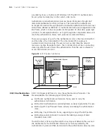
Страница 186: ...only after the user passes the authentication Then the user is allowed to access the network resources Figure 52 802 1X System Architecture 802 1X Authentication Process 802 1X configures EAP frame to carry the authentication information The Standard defines the following types of EAP frames EAP Packet Authentication information frame used to carry the authentication information EAPoL Start Authen...

Страница 187: ...nfigure the 802 1X state of the port The configured items will take effect after the global 802 1X is enabled When 802 1X is enabled on a port the maximum number of MAC address learning which is configured by the command mac address max mac count cannot be configured on the port and vice versa The main 802 1X configuration includes Enabling disabling 802 1X Setting the port access control mode Set...

Страница 188: ...ansmitting and does not permit the user to access the network resources If the authentication flow is passed the port will be switched to the authorized state and permit the user to access the network resources This is the most common case Setting the Port Access Control Method The following commands are used for setting 802 1X access control method on the specified port When no port is specified ...

Страница 189: ...rt By default 802 1X allows up to 256 users on each port for Series 4500 Switches Setting the Authentication in DHCP Environment If in a DHCP environment the users configure static IP addresses you can set 802 1X to disable the Switch to trigger the user ID authentication over them with the following command Perform the following configurations in System View Table 194 Setting the Authentication i...

Страница 190: ...smit the authentication request message to a user for a maximum of 3 times Configuring Timers The following commands are used for configuring the 802 1X timers Perform the following configurations in System View Table 197 Configuring Timers handshake period This timer begins after the user has passed the authentication After setting handshake period system will send the handshake packet by the per...

Страница 191: ...Authenticator will resend the above packet supp timeout value Specify how long the duration of an authentication timeout timer of a user is The value ranges from 10 to 120 in units of second and defaults to 30 tx period Specify the transmission timeout timer After the Authenticator sends a Request Identity request packet which requests the user name or the user name and password together the tx pe...

Страница 192: ...20 minutes they will be disconnected A server group consisting of two RADIUS servers at 10 11 1 1 and 10 11 1 2 respectively is connected to the switch The former one acts as the primary authentication second accounting server The latter one acts as the secondary authentication primary accounting server Set the encryption key as name when the system exchanges packets with the authentication RADIUS...

Страница 193: ... the second authentication accounting RADIUS servers 4500 radius radius1 secondary authentication 10 11 1 2 4500 radius radius1 secondary accounting 10 11 1 1 6 Set the encryption key when the system exchanges packets with the authentication RADIUS server 4500 radius radius1 key authentication name 7 Set the encryption key when the system exchanges packets with the accounting RADIUS server 4500 ra...

Страница 194: ...dle cut enable 20 2000 15 Add a local user and sets its parameter 4500 local user localuser 4500 luser localuser service type lan access 4500 luser localuser password simple localpass 16 Enable the 802 1X globally 4500 dot1x AAA and RADIUS Protocol Configuration Authentication Authorization and Accounting AAA provide a uniform framework used for configuring these three security functions to implem...

Страница 195: ...AS Here NAS controls users and corresponding connections while the RADIUS protocol regulates how to transmit configuration and accounting information between NAS and RADIUS NAS and RADIUS exchange the information with UDP packets During the interaction both sides encrypt the packets with keys before uploading user configuration information for example password to avoid being intercepted or stolen ...

Страница 196: ...username is in userid isp name format the system will take userid part as username for identification and take isp name part as domain name The purpose of introducing ISP domain settings is to support the multi ISP application environment In such an environment one access device might access users of different ISP Because the attributes of ISP users such as username and password formats and so on ...

Страница 197: ...thentication and accounting Table 202 Configuring AAA Scheme Adopted by the ISP Domain By default after an ISP domain is created the default AAA scheme is local You cannot use a RADIUS scheme together with the local or none scheme You can use either scheme or radius scheme command to specify the RADIUS scheme for an ISP domain If both of these two commands are used the latest configuration will ta...

Страница 198: ...th the accounting optional command in RADIUS scheme will no longer send real time accounting update packets or offline accounting packets Perform the following configurations in ISP Domain View Table 206 Enabling the Selection of the RADIUS Accounting Option By default the selection of RADIUS accounting option is disabled The accounting optional command can also be configured in the RADIUS scheme ...

Страница 199: ...their accounts and card numbers by themselves And a server with the self service software is called a self service server Once this function is enabled on the switch users can locate the self service server and perform self management through the following operations Select Change user password on the 802 1X client After the client opens the default explorer IE or Netscape locate the specified URL...

Страница 200: ... Users auto means that the password display mode will be the one specified by the user at the time of configuring the password see the password command in Table 211 for reference and cipher force means that the password display mode of all the accessing users must be in cipher text Setting the Attributes of Local Users Perform the following configurations in Local User View Table 211 Setting Remov...

Страница 201: ...for a local user If both of these two commands are used the latest configuration will take effect Disconnecting a User by Force Sometimes it is necessary to disconnect a user or a category of users by force The system provides the following command to serve this purpose Perform the following configurations in System View Table 212 Disconnecting a User by Force By default no online user will be dis...

Страница 202: ...counting Servers and the Related Attributes Setting the RADIUS Packet Encryption Key Setting Retransmission Times of RADIUS Request Packet Setting the Supported Type of the RADIUS Server Setting the RADIUS Server State Setting the Username Format Transmitted to the RADIUS Server Configuring the Local RADIUS Authentication Server Configuring Source Address for RADIUS Packets Sent by NAS Setting the...

Страница 203: ...IUS scheme created by the system the IP address of the primary authentication server is 127 0 0 1 and the UDP port number is 1645 The authorization information from the RADIUS server is sent to RADIUS clients in authentication response packets so you do not need to specify a separate authorization server In real networking environments you may specify two RADIUS servers as primary and secondary au...

Страница 204: ...ervice port settings on the Switch 4500 units are supposed to be consistent with the port settings on RADIUS server Normally RADIUS accounting service port is 1813 Setting the Maximum Times of Real time Accounting Request Failing to be Responded to A RADIUS server usually checks if a user is online with a timeout timer If the RADIUS server has not received the real time accounting packet from NAS ...

Страница 205: ...ge or not Perform the following configurations in RADIUS Scheme View Table 217 Enabling Disabling the Stopping Accounting Request Buffer By default the stopping accounting request will be saved in the buffer Setting the Maximum Retransmitting Times of Stopping Accounting Request Use this command to set the maximum number of retransmission times that the Switch will attempt to retransmit the saved ...

Страница 206: ...it the RADIUS request packet If it transmits more than the specified retry times NAS considers the communication with the primary and secondary RADIUS servers has been disconnected You can use the following command to set the retransmission times of the RADIUS request packet Perform the following configurations in RADIUS Scheme View Table 221 Setting Retransmission Times of RADIUS Request Packet B...

Страница 207: ...er only Perform the following configurations in RADIUS Scheme View Table 223 Setting the RADIUS Server State By default for the newly created RADIUS scheme the primary and secondary accounting authentication servers are in the state of block for the system RADIUS scheme created by the system the primary accounting authentication servers are in the state of active and the secondary accounting authe...

Страница 208: ...uthorization accounting service is also used in these products and it is called local RADIUS authentication server function Perform the following commands in System View to create delete local RADIUS authentication server Table 226 Creating Deleting the Local RADIUS Authentication Server By default the IP address of the local RADIUS authentication server is 127 0 0 1 and the password is 3com 1 Whe...

Страница 209: ...ent real time accounting it is necessary to set a real time accounting interval After the attribute is set NAS will transmit the accounting information of online users to the RADIUS server regularly You can use the following command to set a real time accounting interval Perform the following configurations in RADIUS Scheme View Table 229 Setting a Real time Accounting Interval minute specifies th...

Страница 210: ...ADIUS Server Response Timer By default the response timeout timer for the RADIUS server is set to three seconds Displaying and Debugging AAA and RADIUS Protocol After the above configuration execute the display command in any view to display the running of the AAA and RADIUS configuration and to verify the effect of the configuration Execute the reset command in User View to reset AAA and RADIUS s...

Страница 211: ...e statistics of local RADIUS authentication server display local server statistics Display the configuration information of all the RADIUS schemes or a specified one display radius radius_scheme_name Display the statistics of RADIUS packets display radius statistics Display the stopping accounting requests saved in buffer without response from System View display stop accounting buffer radius sche...

Страница 212: ...s scheme cams 4500 radius cams primary authentication 10 110 91 146 1812 4500 radius cams key authentication expert 4500 radius cams server type 3com 4500 radius cams user name format without domain 5 Configuration association between domain and RADIUS 4500 radius cams quit 4500 domain cams 4500 isp cams scheme radius scheme cams Configuring the FTP Telnet User Local Authentication Configuring loc...

Страница 213: ...hould modify the server IP address to 127 0 0 1 authentication password to 3com the UDP port number of the authentication server to 1645 Configuring the Switch 4500 General RADIUS Setup The Switch 4500 supports multiple RADIUS schemes which can be assigned to a domain This guide covers the recommended steps to setup the Switch4500 for login Domain and RADIUS Scheme Creation The Switch 4500 can hav...

Страница 214: ... create a new domain as follows 4500 domain Demo New Domain added 4500 isp Demo 5 Change the domain to use the new RADIUS scheme that you have configured 4500 isp demo radius scheme NewSchemeName And that completes the configuration of the new radius server and associating it with a domain Network Login Network login must first be enabled globally by issuing the command dot1x 4500 xx dot1x 802 1X ...

Страница 215: ...S server This can be changed under the RADIUS scheme as follows 4500 xx radius NewSchemeName user name format without domain Switch Login The Switch 4500 supports Switch login to allow multiple users access to the management interface of the switch Once the RADIUS scheme and domain have been set up see Domain and RADIUS Scheme Creation then switch login is enabled By default when you use the usern...

Страница 216: ...ght be some communication fault between NAS and RADIUS server which can be discovered through pinging RADIUS from NAS So ensure there is normal communication between NAS and RADIUS Fault Two RADIUS Packet Cannot be Transmitted to RADIUS Server Troubleshooting The communication lines on physical layer or link layer connecting NAS and the RADIUS server may not work well So ensure the lines work well...

Страница 217: ...mmand 4500 xx debugging radius packet 3Com User Access Level This determines the Access level a user will have with Switch login This can be administrator manager monitor or visitor You may need to add the return list attributes to a dictionary file using the following information VENDOR 3Com 43 ATTRIBUTE 3Com User Access Level 1 Integer 3Com VALUE 3Com User Access Level Visit 0 VALUE 3Com User Ac...

Страница 218: ...216 CHAPTER 11 802 1X CONFIGURATION ...

Страница 219: ...eating the file system creating deleting modifying and renaming a file or a directory and opening a file By default the file system requires that the user confirm before executing commands This prevents unwanted data loss In the Switches supporting XRN the file URL must start with unit No flash the No is the unit ID For example suppose unit ID is 1 and the URL of the text txt file under the root d...

Страница 220: ...system When operating in a stack of switches to clear space the user has to change to the flash of each switch in the stack separately and then clear space in the file system of each switch in turn Use the cd directory command for changing focus to a different switches file system or the unit2 flash device name parameter for the command reset recycle You can use the following commands to perform f...

Страница 221: ...figuration information conveniently The format of the configuration file includes It is saved in the command format Only the non default constants will be saved The organization of commands is based on command views The commands in the same command mode are sorted in one section The sections are separated with a blank line or a comment line a comment line begins with exclamation mark Generally the...

Страница 222: ...h in the Fabric saves the current configuration to its individual configuration file If you do not enter the file name parameter in this command for the Switches that have specified the configuration file for booting the current configurations will be stored to the specified configuration file and for the Switches that have not specified the configuration file for booting the current configuration...

Страница 223: ... the Information of the File used at Startup FTP Overview FTP is a common way to transmit files on the Internet and IP network Before the World Wide Web WWW files were transmitted in the command line mode and FTP was the most popular application Even now FTP is still used widely while most users transmit files via email and Web FTP a TCP IP protocol on the application layer is used for transmittin...

Страница 224: ...nding view Table 246 Configure the FTP Server Authentication and Authorization Device Configuration Default Description Switch Log into the remote FTP server directly with the ftp command You need first get FTP user command and password and then log into the remote FTP server Then you can get the directory and file authority PC Start FTP server and make such settings as username password authority...

Страница 225: ...TP server and the FTP connection timeout The display ftp user command can be used for displaying the detailed information about the connected FTP users Introduction to FTP Client As an additional function provided by the Switch FTP client is an application module and has no configuration functions The Switch connects the FTP clients and the remote server and inputs the command from the clients for...

Страница 226: ...y using Telnet 4500 CAUTION If the flash memory of the Switch is not enough you need to first delete the existing programs in the flash memory and then upload the new ones Type in the right command in User View to establish FTP connection then correct username and password to log into the FTP server 4500 ftp 2 2 2 2 Trying Press CTRL K to abort Connected 220 WFTPD 2 0 service by Texas Imperial Sof...

Страница 227: ...rking Diagram Figure 59 Networking for FTP Configuration 1 Configure the Switch Log into the Switch locally through the Console port or remotely using Telnet 4500 2 Start FTP function and set username password and file directory 4500 ftp server enable 4500 local user switch 4500 luser switch service type ftp ftp directory flash 4500 luser switch password simple hello 3 Run FTP client on the PC and...

Страница 228: ...e 60 TFTP Configuration Table 249 Configuration of the Switch as TFTP Client Downloading Files by means of TFTP To download a file the client sends a request to the TFTP server and then receives data from it and sends acknowledgement to it You can use the following commands to download files by means of TFTP Perform the following configuration in User View Table 250 Download Files by means of TFTP...

Страница 229: ...e TFTP server and upload the config cfg to the TFTP server under the Switch directory for backup purpose Networking Diagram Figure 61 Networking for TFTP Configuration Configuration Procedure 1 Start TFTP server on the PC and set authorized TFTP directory 2 Configure the Switch Log into the Switch locally through the Console port or remotely using Telnet 4500 CAUTION If the flash memory of the Swi...

Страница 230: ...an be forwarded via the port A If the MAC address table contains the MAC_SOURCE the Switch will update the corresponding entry otherwise it will add the new MAC address and the corresponding forwarding port as a new entry to the table The system forwards the packets whose destination addresses can be found in the MAC address table directly through the hardware and broadcasts those packets whose ad...

Страница 231: ...ss table entries the learned entries will be deleted simultaneously Setting MAC Address Aging Time Setting an appropriate aging time implements MAC address aging Too long or too short an aging time set by subscribers will cause the Ethernet switch to flood a large amount of data packets This affects the Switch operation performance If the aging time is set too long the Switch will store a great nu...

Страница 232: ...items reaches the count value You can use the following commands to set the max count of MAC addresses learned by a port Perform the following configuration in Ethernet Port View Table 254 Set the Max Count of MAC Address Learned by a Port By default there is no limit to the MAC addresses learned via the Ethernet port Displaying MAC Address Table After the above configuration execute the display c...

Страница 233: ...0 display mac address MAC ADDR VLAN ID STATE PORT INDEX AGING TIME s 00e0 fc00 3943 1 Learned Ethernet1 0 11 300 0000 0000 5100 1 Learned Ethernet2 0 22 300 0020 9c08 e774 1 Learned Ethernet2 0 7 288 0000 0000 5000 1 Learned Ethernet2 0 3 143 4 mac address es found MAC Address Table Management Configuration Example Networking Requirements The user logs into the Switch via the Console port to confi...

Страница 234: ...net1 0 2 500 00 e0 fc 5e b1 fb 1 Learned Ethernet1 0 2 500 00 e0 fc 55 f1 16 1 Learned Ethernet1 0 2 500 4 mac address es found Device Management With the device management function the Switch can display the current running state and event debugging information about the unit thereby implementing the maintenance and management of the state and communication of the physical devices In addition the...

Страница 235: ...ROM program file from a remote end to the Switch via FTP and then use this command to upgrade the BootROM Perform the following configuration in User View Table 259 Upgrade BootROM Displaying and Debugging Device Management After the above configuration execute display command in all views to display the running of the device management configuration and to verify the effect of the configuration O...

Страница 236: ...p and boot app from the remote FTP server Networking Diagram Figure 65 Networking for FTP Configuration Configuration Procedure 1 Configure FTP server parameters on the PC Define a user named as Switch password hello read and write authority over the Switch directory on the PC 2 Configure the Switch The Switch has been configured with a Telnet user named as user as 3 level user with password hello...

Страница 237: ... server ftp get switch app ftp get boot app 6 Use the quit command to release the FTP connection and return to User View ftp quit 4500 7 Upgrade BootROM 4500 boot bootrom boot app This will update BootRom file on unit 1 Continue Y N y Upgrading BOOTROM please wait Upgrade BOOTROM succeeded 8 Use the boot boot loader command to specify the downloaded program as the application at the next login and...

Страница 238: ...mmands for displaying the system running state Commands for displaying the system statistics information For the display commands related to each protocol and different ports refer to the relevant chapters The following display commands are used for displaying the system state and the statistics information Configuration agent is one of the XRN features You can log into one Switch of the Fabric to...

Страница 239: ...es can control the outputs of the debugging information Protocol debugging Switch controls the debugging output of a protocol Terminal debugging Switch controls the debugging output on a specified user screen Figure 66 illustrates the relationship between two Switches Operation Command Display the system clock display clock Display the system version display version Display the saved configuration...

Страница 240: ...e device You can view the debugging information including that of the master and the device in which the login port resides You can enable the logging debugging and trap information switches within the fabric by executing the info center switch on all command Synchronization is a process that each switch sends its own information to the other switches in the fabric and meantime receives informatio...

Страница 241: ...n be used to check the network connection and if the host is reachable Perform the following operation in all views Table 268 The ping Command The output of the command includes The response to each ping message If no response packet is received when time is out Request time out information appears Otherwise the data bytes the packet sequence number TTL and the round trip time of the response pack...

Страница 242: ... The purpose to carry out the process is to record the source address of each ICMP TTL timeout message so as to provide the route of an IP packet to the destination Perform the following operation in all views Figure 67 The tracert Command Logging Function Introduction to Info center The Info center serves as an information center of the system software modules The logging system is responsible fo...

Страница 243: ...p is the date and it can be changed to boot format or none format through the command info center timestamp log date boot none The date format of timestamp is mm dd hh mm ss yyyy mm is the month field such as Jan Feb Mar Apr May Jun Jul Aug Sep Oct Nov Dec dd is the day field if the day is less than the 10th one blank should be added such as 7 hh mm ss is the time field hh is from 00 to 23 mm and ...

Страница 244: ...le DHCC DHCP Client module DHCP Dynamic host configuration protocol module DRV Driver module DRV_MNT Driver maintenance module ESP End station polling module ETH Ethernet module FIB Forwarding module FTM Fabric topology management module FTMCMD Fabric topology management command line module FTPS FTP server module HA High availability module HTTPD HTTP server module IFNET Interface management modul...

Страница 245: ...ty Note that there is a slash between severity and digest 6 Digest The digest is abbreviation it represent the abstract of contents RDS Radius module RM Routing management RMON Remote monitor module RSA Revest shamir and adleman encryption system RTPRO Routing protocol SHELL User interface SNMP Simple network management protocol SOCKET Socket SSH Secure shell module STP Spanning tree protocol modu...

Страница 246: ...on can be filtered in accordance with the modules The output language can be selected between Chinese and English 1 Sending the information to loghost Table 273 Sending the Information to Loghost Output direction Channel number Default channel name Console 0 console Monitor 1 monitor Info center loghost 2 loghost Trap buffer 3 trapbuf Logging buffer 4 logbuf snmp 5 snmpagent Device Configuration D...

Страница 247: ...sponding module before defining output debugging information Enable terminal display function You can view debugging information after enabling terminal display function Device Configuration Default Value Configuration Description Switch Enable info center By default info center is enabled Other configurations are valid only if the info center is enabled Set the information output direction to mon...

Страница 248: ...guration Description Switch Enable info center By default info center is enabled Other configurations are valid only if the info center is enabled Set the information output direction to trapbuffer You can configure the size of the trap buffer at the same time Set information source You can define which modules and information to be sent out and the time stamp format of information and so on You m...

Страница 249: ... can define the information that is sent to the control terminal such as generated by which modules information type information level and so on Perform the following operation in System View Device Configuration Default Value Configuration Description Switch Enable info center By default info center is enabled Other configurations are valid only if the info center is enabled Set the information o...

Страница 250: ...he debugging Switch of those modules You can use the following commands to configure log information debugging information and the time stamp output format of trap information Perform the following operation in System View Table 281 Configuring the Output Format of Time stamp 4 Configuring loghost The configuration on the loghost must be the same with that on the Switch For related configuration s...

Страница 251: ...to the channel that corresponds to the Console direction Every channel has been set with a default record whose module name is default and the module number is 0xffff0000 However for different channels the default record may have different default settings of log trap and debugging When there is no specific configuration record for a module in the channel use the default one If you want to view th...

Страница 252: ...rmation classification and outputting 2 Configuring to output information to Telnet terminal or dumb terminal Perform the following operation in System View Table 288 Configuring to Output Information to Telnet Terminal or Dumb Terminal Operation Command Configure the output format of the time stamp info center timestamp log trap debugging boot date none Output time stamp is disabled undo info cen...

Страница 253: ...sers at the same time some configuration parameters should be shared among the users such as module based filtering settings and severity threshold When a user modifies these settings it will be reflected on other clients If you want to view the debugging information of some modules on the Switch you must select debugging as the information type when configuring information source meantime using t...

Страница 254: ...Log Buffer 3 Configuring the information source on the Switch With this configuration you can define the information that is sent to the log buffer generated by which modules information type information level and so on Operation Command Enable terminal display function of log debugging and trap information terminal monitor Disable terminal display function of the above information undo terminal m...

Страница 255: ...ging as the information type when configuring the information source meantime using the debugging command to turn on the debugging Switch of those modules You can use the following commands to configure log information debugging information and the time stamp output format of trap information Perform the following operation in System View Table 295 Configuring the Output Format of Time stamp Sendi...

Страница 256: ... corresponds to the Console direction Every channel has been set with a default record whose module name is default and the module number is 0xffff0000 However for different channels the default record may have different default settings of log trap and debugging When there is no specific configuration record for a module in the channel use the default one If you want to view the debugging informa...

Страница 257: ...ents all the modules level refers to the severity levels severity specifies the severity level of information The information with the level below it will not be output channel number specifies the channel number and channel name specifies the channel name When defining the information sent to SNMP NM channel number or channel name must be set to the channel that corresponds to Console direction O...

Страница 258: ...n get correct information from the network management workstation Turning On Off the Information Synchronization Switch in Fabric After the forming of a Fabric by Switches which support XRN the log debugging and trap information among the Switches is synchronous The synchronization process is as follows each Switch sends its own information to other Switches in the Fabric and meantime receives the...

Страница 259: ...x Loghost Networking Requirement The networking requirements are as follows Sending the log information of the Switch to Unix loghost The IP address of the loghost is 202 38 1 10 The information with the severity level above informational will be sent to the loghost The output language is English The modules that allowed to output information are ARP and IP Operation Command Turn on the informatio...

Страница 260: ... on SunOS 4 0 and the operation on Unix operation system produced by other manufactures is generally the same to the operation on SunOS 4 0 a Perform the following command as the super user root mkdir var log 4500 touch var log 4500 information b Edit file etc syslog conf as the super user root add the following selector actor pairs 4500 configuration messages local4 info var log 4500 information ...

Страница 261: ...log information of the Switch to Linux loghost The IP address of the loghost is 202 38 1 10 The information with the severity level above informational will be sent to the loghost The output language is English All modules are allowed to output information Networking diagram Figure 72 Schematic Diagram of Configuration Configuration Procedure 1 Enabling info center 4500 info center enable Set the ...

Страница 262: ...ectly c After the establishment of information log file and the revision of etc syslog conf you should view the number of syslogd system daemon through the following command kill syslogd daemon and reuse r option the start syslogd in daemon ps ae grep syslogd 147 kill 9 147 syslogd r For Linux loghost you must ensure that syslogd daemon is started by r option After the above operation the Switch s...

Страница 263: ...tly and implement the fault diagnosis capacity planning and report generating SNMP adopts the polling mechanism and provides the most basic function set It is most applicable to the small sized fast speed and low cost environment It only requires the unverified transport layer protocol UDP and is thus widely supported by many other products In terms of structure SNMP can be divided into two parts ...

Страница 264: ...d it is the set defined by the standard variables of the monitored network device In the above figure the managed object B can be uniquely specified by a string of numbers 1 2 1 1 The number string is the Object Identifier of the managed object The current SNMP Agent of the Switch supports SNMP V1 V2C and V3 The MIBs supported are listed in the following table Table 306 MIBs Supported by the Switc...

Страница 265: ...ed with a character string which is called Community Name The various communities can have read only or read write access mode The community with read only authority can only query the device information whereas the community with read write authority can also configure the device You can use the following commands to set the community name Perform the following configuration in System View Table ...

Страница 266: ...owing commands to set the system information Perform the following configuration in System View Table 311 Set SNMP System Information Operation Command Enable to send trap snmp agent trap enable configuration flash ospf process id ospf trap list standard authentication coldstart linkdown linkup warmstart system Disable to send trap undo snmp agent trap enable bgp backwardtransition established con...

Страница 267: ...ess of Trap Adding Deleting a User to from an SNMP Group You can use the following commands to add or delete a user to from an SNMP group Perform the following configuration in System View Restore the default SNMP System Information of the Switch undo snmp agent sys info contact location version v1 v2c v3 all Operation Command Operation Command Set the engine ID of the device snmp agent local engi...

Страница 268: ...le Disable a Port Transmitting Trap Information SNMP Agent Disabling SNMP Agent To disable SNMP Agent perform the following configuration in System View Table 319 Disable SNMP Agent Operation Command Add a user to an SNMP group snmp agent usm user v1 v2c username groupname acl acl list snmp agent usm user v3 username groupname authentication mode md5 sha authpassstring privacy mode des56 privpasss...

Страница 269: ...tact and Switch location and enable the Switch to send trap packet Operation Command Display the statistics information about SNMP packets display snmp agent statistics Display the engine ID of the active device display snmp agent local engineid remote engineid Display the group name the security mode the states for all types of views and the storage mode of each group of the Switch display snmp a...

Страница 270: ...face2 ip address 129 102 0 1 255 255 255 0 4 Set the administrator ID contact and the physical location of the Switch 4500 snmp agent sys info contact Mr Wang Tel 3306 4500 snmp agent sys info location telephone closet 3rd floor 5 Enable SNMP agent to send the trap to Network Management Station whose ip address is 129 102 149 23 The SNMP community is public 4500 snmp agent trap enable standard aut...

Страница 271: ...0 snmp agent group v3 sdsdsd 4500 snmp agent usm user v3 paul sdsdsd authentication mode md5 hello 4500 snmp agent mib view included ViewDefault snmpUsmMIB 4500 snmp agent mib view included ViewDefault snmpVacmMIB 4500 display snmp agent mib view View name ViewDefault MIB Subtree iso Subtree mask Storage type nonVolatile View Type included View status active View name ViewDefault MIB Subtree snmpU...

Страница 272: ... networks RMON allows multiple monitors It can collect data in two ways One is to collect data with a special RMON probe NMS directly obtains the management information from the RMON probe and controls the network resource In this way it can obtain all the information of the RMON MIB Another way is to implant the RMON Agent directly into the network devices such as a Switch Hub etc so that the dev...

Страница 273: ...use the following commands to add delete an entry to from the event table Perform the following configuration in System View Table 322 Add Delete an Entry to from the Event Table Adding Deleting an Entry to from the History Control Terminal The history data management helps you set the history data collection periodical data collection and storage of the specified ports The sampling information in...

Страница 274: ...ebugging RMON After the above configuration execute the display command in all views to display the running of the RMON configuration and to verify the effect of the configuration Table 326 Display and Debug RMON Operation Command Add an entry to the history control terminal rmon history entry number buckets number interval sampling interval owner text string Delete an entry from the history contr...

Страница 275: ...e Ethernet1 0 1 Received octets 270149 packets 1954 broadcast packets 1570 multicast packets 365 undersized packets 0 oversized packets 0 fragments packets 0 jabbers packets 0 CRC alignment errors 0 collisions 0 Dropped packet events due to lack of resources 0 Packets received according to length in octets 64 644 65 127 518 128 255 688 256 511 101 512 1023 3 1024 1518 0 Display the alarm informati...

Страница 276: ...ection is established both ends begin to negotiate the SSH version If they can work together in harmony they enter the key algorithm negotiation stage Otherwise the server clears the TCP connection Key negotiation stage Both ends negotiate key algorithm and compute session key The server randomly generates its RSA key and sends the public key to the client The client figures out session key based ...

Страница 277: ...nd the session key is generated randomly Encryption is used in exchanging session key and RSA authentication achieves key exchange without transfer over the network SSH can protect server client data security The authentication will also start even if the username received is not configured at the server so malicious intruders cannot judge whether a username they key in exists or not This is also ...

Страница 278: ...nerate local key pairs you just need to execute the command once with no further action required even after the system is rebooted Configuring Authentication Type For a new user you must specify authentication type Otherwise they cannot access the Switch Perform the following configurations in System View Table 329 Configuring Authentication Type If the configuration is RSA authentication type the...

Страница 279: ...gure password authentication for the SSH user Perform the following configurations in System View Table 333 Configuring Public Key When entering the public key edit view with the rsa peer public key command you can begin editing the public key with the public key code begin command You can key in a blank space between characters since the system can remove the blank space automatically But the pub...

Страница 280: ...tly supports SSH Server 1 5 so you have to choose 1 5 or an earlier version Specifying RSA private key file If you specify RSA authentication for the SSH user you must specify RSA private key file The RSA key which includes the public key and private key are generated by the client software The former is configured in the server Switch and the latter is in the client The following description take...

Страница 281: ...eration process has finished save the generated public and private keys to files using the Save buttons Run the sshkey program This converts SSH public key to the format required by the Switch Open the public key file generated by puttygen then click the Convert button ...

Страница 282: ...pad and the following lines of text before the existing text rsa peer public key mykey public key code begin where myKey is a name used to identify the key within the Switch you may choose any name for this Then add the following after the existing text public key code end peer end Also remove any blank lines from the file The file should look like this ...

Страница 283: ...ith a bat extension for example keys bat This file can be transferred to the Switch using FTP or TFTP The key is installed using the execute command in the System view 4500 execute keys bat Specifying Server IP Address Start PuTTY program and the client configuration interface pops up ...

Страница 284: ...the IP address of the Switch for example 10 110 28 10 You can also input the IP address of an interface in UP state but its route to SSH client PC must be reachable Selecting SSH Protocol Select SSH for the Protocol item Choosing SSH Version Click the left menu Category Connection SSH to enter the interface shown in following figure ...

Страница 285: ...ou can select 1 as shown in the above figure Specifying RSA Private Key File If you want to enable RSA authentication you must specify RSA private key file which is not required for password authentication Click SSH Auth to enter the interface as shown in the following figure ...

Страница 286: ...File Select interface Choose a desired file and click OK Opening SSH Connection Click Open to enter SSH client interface If it runs normally you are prompted to enter username and password See the following figure Figure 87 SSH client interface Key in the correct username and password and log into SSH connection ...

Страница 287: ...ce this operation is unnecessary 2 For password authentication mode 4500 user interface vty 0 4 4500 ui vty0 4 authentication mode scheme 4500 ui vty0 4 protocol inbound ssh 4500 local user client001 4500 luser client001 password simple 3com 4500 luser client001 service type ssh 4500 ssh user client001 authentication type password Select the default values for SSH authentication timeout value retr...

Страница 288: ...at file containing keys then you need not perform this step 4500 rsa peer public key switch002 4500 rsa public public key code begin 4500 key code 308186028180739A291ABDA704F5D93DC8FDF84C427463 4500 key code 1991C164B0DF178C55FA833591C7D47D5381D09CE82913 4500 key code D7EDF9C08511D83CA4ED2B30B809808EB0D1F52D045DE4 4500 key code 0861B74A0E135523CCD74CAC61F8E58C452B2F3F2DA0DC 4500 key code C48E33063...

Страница 289: ...a password ages out its user must update it otherwise the user cannot log in the switch Password update after a password ages out the user can update it when logging in the switch Alert before password expiration users can set their respective alert times When a user logs in the system and the password is about to age out that is the remaining usable time of the password is no more than the set al...

Страница 290: ...sswords and save the passwords in ciphertext mode in the configuration file Telnet SSH super and FTP passwords Login attempts limitation and failure procession You can use this function to enable the switch to limit the times of login attempts allowed for each user If the login attempt times of a user exceeds the configured maximum times the user fails the login In this case the switch operates in...

Страница 291: ...d limitation the configured User blacklist If the maximum attempt times is exceeded the user cannot log in the switch and is added to the blacklist by the switch All users in the blacklist are not allowed to log in the switch For the user inhibited from login for a certain time period the switch will remove the user from the blacklist when the time period is used out For the user inhibited from lo...

Страница 292: ...ert time In this case the system alerts the user to the remaining time in days before the password expires and prompt the user to change the password If the user chooses to change the password and change it successfully the system saves the new password restarts the password aging procedure and at the same time allows the user to log in If the user chooses to change the password but fails to do so...

Страница 293: ...ngle password for a long time or using an old password that was once used to enhance the security CAUTION When adding a new record but the number of the recorded history passwords exceeds the configured maximum number the system replaces the oldest record of the user with the new one CAUTION When you configure the maximum number of history password records if the number of the history password rec...

Страница 294: ...d control history record super level level value Executing this command without the level level value option will remove the history records of all super passwords Executing this command with the level level value option will remove the history records of the super password for the users at the specified level Table 340 Configure User Login Password in Encryption Mode Operation Command Description...

Страница 295: ...procedure starts from the time the local remote server of the switch receives the user name and ends at the time the user authentication is completed Whether the user is authenticated on the local server or on a remote server is determined by the related AAA configuration For more details see the secure module of this guide If a password authentication is not completed within the configured authen...

Страница 296: ... 343 Configuring the Timeout for User Password Authentication Operation Command Description Enter system view system view Configure the timeout time of user password authentication password control authentication time out authentication time out By default it is 60 seconds Table 344 Displaying Password Control Operation Command Display the information about the global password control for all user...

Страница 297: ...ontrol super aging 10 The super password aging time is 10 days Display the information about the global password control for all users 4500 display password control Global password settings for all users Password Aging Enabled 90 days Password Length Enabled 10 Characters Password History Enabled Max history record num 6 Password alert before expire 7 days Password Authentication timeout 60 second...

Страница 298: ...296 CHAPTER 13 PASSWORD CONTROL CONFIGURATION OPERATIONS ...

Страница 299: ...is disabled and the user configurable bootrom password is lost there is no recovery mechanism available In this instance the Switch will need to be returned to 3Com for repair The following commands are all executed from the Bootrom directly via the console CLI Commands Controlling Bootrom Access Access to the bootrom is enabled by default on your Switch To disable access enter the following comma...

Страница 300: ... switch startup mode 0 Reboot Enter your choice 0 9 Enter the boot menu number to display that menu option Displaying all Files in Flash Enter boot menu option 3 to display the following Boot menu choice 3 Free Space 10460160 bytes The current application file is s4b03_01_04s56 app Table 345 displays the configuration files Table 345 Configuration Files File Number File Size bytes File Name 1 7147...

Страница 301: ...h is followed by either of the following entries Simple this enables you to read and or change a password and send the configuration file via TFTP back into the Switch Cipher change this word to simple and replace the encrypted password with a plain text password and send the configuration file via TFTP back into the Switch The manager and monitor passwords can be modified in the same way Bootrom ...

Страница 302: ... based on switch mac address is invalid The current mode is enable bootrom password recovery Are you sure to disable bootrom password recovery Yes or No Y N This option allows the user to disable the fixed unit unique password recovery mechanism If this is disabled and the bootrom password recovery is lost then a recovery will not be possible In this instance the Switch will need to be returned to...

Страница 303: ...Com products and are not supported by 3Com Configuring Microsoft IAS RADIUS 3Com has successfully installed and tested Microsoft IAS RADIUS running on a Windows server in a network with Switch 4500 deployed The following steps are required to setup a RADIUS server using the Microsoft IAS RADIUS application You will need to use the Install CD for Microsoft Windows 2000 Server to complete the proces...

Страница 304: ...choose Properties select Change Mode c Add a user that is allowed to use the network Go to Active Directory Users and Computers from the left hand window right click the Users folder and choose New User as shown below d Follow the wizard to create a user enter the required information at each stage ...

Страница 305: ...d select Reset Password 3 Enable the server as a certificate server To use EAP TLS certificate based authentication you need to enable the Certificate services in windows Make sure you have completed step 2 and created the DNS server before enabling Certificate services You will not be able to create the DNS server after certification has been enabled a Go to Control Panel Add Remove Programs Add ...

Страница 306: ... location on the Data Storage Location window To complete the installation and set up of the certificates server the wizard will require the Install CD for Microsoft Windows 2000 Server 4 Install the Internet Authentication Service IAS program a Go to Control Panel Add Remove Programs Add Remove Windows Components Enable Networking Services and ensure Internet Authentication Service component is c...

Страница 307: ...tification Authority and right click Policy Settings under your Certificate Authority server b Select New Certificate to Issue c Select Authenticated Session and select OK d Go to Programs Administrative Tools Active Directory Users and Computers and right click your active directory domain Select Properties ...

Страница 308: ...omputer Configuration Windows Settings Security Settings Public Key Policies and right click Automatic Certificate Request Settings Select New Automatic Certificate Request g The Certificate Request Wizard will start Select Next Computer certificate template and click Next h Ensure that your Certificate Authority is checked then click Next Review the Policy Change Information and click Finish ...

Страница 309: ...and Select New Client b Enter a name for your device that supports IEEE 802 1X Click Next c Enter the IP address of your device that supports IEEE 802 1X and set a shared secret Select Finish Leave all the other settings as default d Right click Remote Access Policies and select New Remote Access Policy e Give the policy a name for example EAP TLS and select Next f Click Add g Set the conditions f...

Страница 310: ...propriate certificate and click OK There should be at least one certificate This is the certificate that has been created during the installation of the Certification Authority Service Windows may ask if you wish to view the Help topic for EAP Select No if you want to continue with the installation l Click Finish For EAP TLS to work correctly it is important that there is only one policy configure...

Страница 311: ... certsrv b When you are prompted for a login enter the user account name and password that you will be using for the certificate c Select Request a certificate and click Next There are two ways to request a certificate the Advanced Request or the Standard Request The following steps show an Advanced Request The Standard Request differs in the way the certificate is stored on the local computer it ...

Страница 312: ... and click Next e Select the first option and click Next f Either copy the settings from the screenshot below or choose different key options Click Save to save the PKCS 10 file The PKCS 10 file is used to generate a certificate g You will receive this warning message select Yes ...

Страница 313: ...e a portable certificate using PKCS 10 click the Home hyperlink at the top right of the CA Webpage i Select Request a certificate Next Advanced request Next j Select the second option as shown in the screenshot below and click Next k Open the previously saved PKCS 10 certificate file in Notepad select all Control a and copy Control c as shown below ...

Страница 314: ...ve the certificate Save the file as DER encoded Click on the Download CA certification path hyperlink to save the PKCS 7 and select Save The certificate is also installed on the Certification Authority You can verify this in the CA Administration tool under Issued Certificates The PKCS 7 file is not actually required for IEEE 802 1X functionality n Install both PKCS 10 and PKCS 7 files on the work...

Страница 315: ...xt screen as is click Next followed by Finish and OK This will install the certificate q Launch the Certification Authority management tool on the server and expand the Issued Certificates folder You should see the newly created certificate r Double click the certificate that was generated by the client and select the Details tab ...

Страница 316: ...ck Next when the wizard is launched Save the certificate using DER x 509 encoding select DER encoded binary followed by Next Provide a name for the certificate and save it to a specified location Click Finish and followed by OK t Exit the Certification Authority management tool and launch the Active Directory Users and Computers management tool Ensure that the Advanced Features are enabled in the ...

Страница 317: ...lick Open Click OK w In the Security Identity Mapping screen click OK to close it x Close the Active Directory Users and Domains management tool This completes the configuration of the RADIUS server 10 Configure Microsoft IAS RADIUS Server for Switch Login a Create a Windows Group that contains the users that are allowed access to the Switch 4500 Add an additional user as a member of this windows ...

Страница 318: ... CLIENT SETUP b Create a new remote access policy under IAS and name it Switch Login Select Next c Specify Switch Login to match the users in the switch access group select Next d Allow Switch Login to grant access to these users select Next ...

Страница 319: ...Setting Up a RADIUS Server 317 e Use the Edit button to change the Service Type to Administrative f Add a Vendor specific attribute to indicate the access level that should be provided ...

Страница 320: ... are prompted to select a certificate it could be that there are additional active certificates on your client computer select the certificate that you have installed for this specific Certification Authority server If you encounter problems check the Event Viewer and the System Log on the server to determine what is what is happening and possible causes for the problems Configuring Auto VLAN and ...

Страница 321: ...Computers a For example to create one group that will represent VLAN 4 select the Users folder from the domain see below b Name the VLAN Group with a descriptive name that describes the function of the VLAN Group for example VLAN4 Check Global in the Group Scope box and Security in the Group Type box click OK c Select the group right click and select Properties Select the Members tab add the users...

Страница 322: ...ministrative Tools Internet Authentication Service and select Remote Access Policies Select the policy that you configured earlier right click and select Properties e Click Add to add policy membership f Select the Windows Groups attribute type and select Add and Add again ...

Страница 323: ...ou have just created and click Add and then OK to confirm h Click OK again to return you to the Security Policy properties i Click Edit Profile and select the Advanced tab Click Add Refer to Table 346 and Table 348 for the RADIUS attributes to add to the profile ...

Страница 324: ...k Ensure that the Attribute value is set to 802 and click OK l Click OK again on the Multivalued Attribute Information screen to return to the Add Attributes screen Table 347 For Auto VLAN Return String Comment Tunnel Medium type 802 Tunnel Private Group ID 2 VLAN value Tunnel Type VLAN Table 349 For Auto QoS Return String Comment Filter id profile student QoS Profile name ...

Страница 325: ...d n Click Add ensure that the Attribute value is set to 4 Attribute value in string format and click OK This value represents the VLAN ID o Click OK again on the Multivalued Attribute Information screen to return to the Add Attributes screen Select the Tunnel Type entry and click Add ...

Страница 326: ...re that there is a DHCP server connected to the Switch that resides on a switch port that is an untagged member of VLAN 4 The RADIUS server should reside in the same VLAN as the workstation Once authenticated the Switch will receive VLAN information from the RADIUS server and will place the switch port in the associated VLAN For troubleshooting you can use the Event Viewer on both the workstation ...

Страница 327: ... as a RADIUS server for networks with the Switch 4500 follow these steps 1 Open file eap ini in radius service and remove the before the MD5 Challenge Line This enables the MD5 challenge 2 Open file radius ini in radius service and change the log level to 5 ...

Страница 328: ...start it Funk RADIUS is now ready to run If you intend to use auto VLAN and QoS you will need to create VLAN and QoS profiles on the 3Com Switch 4500 and follow the instructions in Configuring Auto VLAN and QoS for Funk RADIUS 4 Start the Funk RADIUS program select Servers from the left hand list and select Local Radius server Select Connect to start listening for clients 5 To add a user select Us...

Страница 329: ...tive 6 Enter the shared secret to encrypt the authentication data The shared secret must be identical on the Switch 4500 and the RADIUS Server a Select RAS Clients from the left hand list enter a Client name the IP address and the Shared secret SWITCH 4500 ...

Страница 330: ...es will now appear as potential Return list attributes for every user 2 After saving the edited radius dct file stop and restart the Funk RADIUS service 3 To use these return list attributes they need to be assigned to a user or group Create a new user and add the return list attributes shown in Table 350 and Table 352 Table 350 Summary of auto VLAN attributes Table 352 Summary of QoS attributes T...

Страница 331: ...reeRADIUS To configure FreeRADIUS as a RADIUS server for networks with the Switch 4500 follow these steps 1 Add each Switch 4500 as a RADIUS client to the FreeRADIUS server a Locate the existing file clients conf in usr local etc raddb b Add an entry in clients conf for the Switch 4500 you wish to administer For example client xxx xxx xxx xxx secret a shared secret shortname a short name Where xxx...

Страница 332: ...p Auto VLAN and QOS using FreeRADIUS It is slightly more complex to set up auto VLAN and QoS using FreeRADIUS as the dictionary file needs to be specially updated 1 Update the dictionary tunnel file with the following lines ATTRIBUTE Tunnel Type 64 integerhas_tag ATTRIBUTE Tunnel Medium Type 65 integerhas_tag ATTRIBUTE Tunnel Private Group Id 81 stringhas_tag VALUE Tunnel Type VLAN 13 VALUE Tunnel...

Страница 333: ...hipped with Windows XP has a security issue which affects the port authentication operation If the RADIUS client is configured to use EAP MD5 after a user logs off then the next user to log on will remain authorized with the original user s credentials This occurs because the Microsoft client does not generate an EAPOL Logoff message when the user logs off which leaves the port authorized To reduc...

Страница 334: ...m ID can be found when running the Aegis Client application for the first time To apply the license key a Run the Aegis Client software b Go to Aegis Client Register and select Help on the menu c Copy the License ID indicated at the bottom of the dialog box into the License ID field d Copy the License Key provided in the email from Meetinghouse into the License Key field e Press OK 2 Configuring t...

Страница 335: ...tion e Restart the client either by rebooting or stopping and re starting the service f Click the OK button then return to the Aegis Client main interface To restart the client press the button with the red cross If authentication is successful the icon will turn green ...

Страница 336: ...334 APPENDIX B RADIUS SERVER AND RADIUS CLIENT SETUP ...

Страница 337: ...g the RADIUS protocol Users that already exist on the TACACS server can be authorized using the TACACS or RADIUS server an optional VLAN and QoS profile can be applied to the user Network administrators can also be authorized using the built in RADIUS server providing centralized access to 3Com Switches The remainder of this appendix describes how to setup Cisco Secure ACS v3 3 to operate using RA...

Страница 338: ...nto the Cisco Secure ACS interface follow these steps 1 Select Network Configuration from the left hand side 2 Select Add Entry from under AAA Clients 3 Enter the details of the 3Com Switch Spaces are not permitted in the AAA Client Host name An example is shown below 4 Select Submit Do not restart the ACS server at this stage ...

Страница 339: ...ide 6 Select RADIUS IETF from the list under Interface Configuration 7 Check the RADIUS attributes that you wish to install If you want to use auto VLAN and QoS ensure that you have the following options selected for both the User and Group Filter ID Tunnel Type Tunnel Medium Type Tunnel Private Group I ...

Страница 340: ...estart Adding a User for Network Login Existing users on a network with a Secure ACS server can be authorized using the TACACS or RADIUS server New users connected through a Switch 4500 to the network need to be authorized via the RADIUS server An optional VLAN and QoS profile can be applied to the user Follow these steps to add a user for Network Login 1 Select User Setup from the left hand side ...

Страница 341: ...ightly more complex as 3Com specific RADIUS attributes need to be returned to the 3Com Switch 4500 These RADIUS attributes define the access level of the user to the management interface Follow these steps 1 Add the required RADIUS attributes to the Cisco Secure ACS server by editing an ini file and compiling it into the Secure ACS RADIUS server using an application called csutil exe For example a...

Страница 342: ... will stop the Cisco Secure ACS server add the RADIUS information by adding the contents of 3Com ini to UDV User Defined Vendor slot 0 and then restart the server Once complete log into the Secure ACS server again and complete steps 2 and 3 2 To use the new RADIUS attributes a client needs to be a user of RADIUS 3Com attributes Select Network Configuration from the left hand side and select an exi...

Страница 343: ...erface Configuration followed by RADIUS 3Com a Ensure that the 3Com User Access Level option is selected for both User and Group setup as shown below 5 Select User Setup and either modify the attributes of an existing user select Find to display the User List in the right hand window or Add a new user see Adding a User for Network Login Set the user s access level to the 3Com Switch 4500 by ...

Страница 344: ...re there should be the option for configuring the access level as shown below 6 In the RADIUS 3Com Attribute box check 3Com User Access Level and select Administrator from the pull down list see below 7 Select Submit The Switch 4500 can now be managed by the Network Administrator through the CISCO Secure ACS server ...

Отзывы: