201
9
.
0
1
.
1
8
005
Ⓐ
表4
OM-K0572E 00
4
表1
3
C. CAUTION
q
The system function normally in the environment where the temperature is at 0-40˚C. humidity at 10-85% RH, atmospteric
pressure at 500-1060hPa, and no moisture condensation in the Unit. Use at outside of these Limits may cause malfunction.
w
Store the system in the place where the temperature is at -10-60˚C, humidity at 10-85% RH, and the system is not
subject to air with dust, sulfur, or salinity.
e
Do not install system next to RF noise sources malfunctions can occur.
r
Install equipment so that the power supply cord can be pulled out without hindrance in event of emergency.
t
This system is not approved for use in flammable or explosive environments or with flammable or explosive materials.
y
Never oil the bearings. This attachment is assembled with permanently greased bearings.
u
Please check the motor and handpiece prior to each use for vibration, abnormal noises, heat, and rough or stiff rotation.
If any of the above conditions are beyond acceptable limits, please send the system to NAKANISHI for service.
i
Never move the Chuck Control Ring to Open while the motor is running, the motor and attachment will be damaged.
Only change tool with the motor completely stopped.
o
When using large cutting tools, tools with a head diameter larger than 4mm rotate the motor and attachment at slow
speed. It is very easy to bend and break large cutting tools at high rotation speeds.
!0
If the motor protection circuit repetitively activates and stops the motor, you are using too much force. Please use
less hand force and continue the operation. Heavy handed usage will result in dramatically shortened motor,
attachment and tool life.
!1
Please clean the chuck and spindle center shaft weekly as failure to do this can cause contaminants to build up in
the chuck and increase runout or reduce the clamping strength of the chuck.
!2
Do not disassemble or alter the product by yourself.
!3
Be sure to replace fuse with the correct type and rating.
!4
Do not spill any liquid on the controls.
!5
Please be careful not to be injured by the grinder or bur.
!6
Be sure to turn the power off before cleaning and maintenance of the Handpiece.
D. NOTICE
q
Do not tighten the collet without mounting a cutting tool or dummy bur as this will result in damage to the collet and spindle.
w
Don't use pencils, pens or other sharp objects on the Front Panel buttons.
e
User is solely responsible for maintaining control of operation, maintenance and periodic inspection of the system.
r
Equipment to be send back to manufacturer for servicing / repair.
t
Only use with original power supply cord. In case of damage, contact NSK / NAKANISHI service center.
Fig. 2
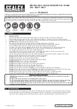
q
Control Unit
w
Speed Control Knob
e
Speed Display
r
Load Meter
t
Forward / Reverse Selector Switch
y
Forward / Reverse LED
u
Motor A Switch
i
Motor A LED
o
Motor A Connector
!0
FIXPEED Switch
!1
FIXPEED LED
!2
Motor B Switch
!3
Motor B LED
!4
Motor B Connector
!5
Power Switch
!6
Handpiece Holder
!7
Optional Foot Pedal (FC-64)
!8
Motor Handpiece
(IR-310,ENK-410S)
!9
NAKANISHI Smart Switch
@0
Handpiece Stand
@1
Foot Pedal Connector
@2
Power Cord
@3
Power Connector Assembly
S
Component Names
Fig. 1
17
18
20
19
2
3
1
10
11
16
12
8
7
6
5
13
14
15
4
9
22
23
21
3
4
S
Setting Up the Control Unit
1.Connecting the Motor/Attachment
Insert the motor cord plug into the Motor A Connector
o
or the
Motor B Connector
!4
, and align the pin on the plug with the
groove on the connector and tighten the motor cord plug nut.
(
Fig. 3
)
2.Connecting the Optional Foot Pedal
Insert the foot pedal cord plug into the Foot Pedal Connector
@1
and align the pin on the plug with the groove on the connector.
(
Fig. 4
)
3.Connecting the Power Cord
Insert the Power Cord
@2
plug into the Power Connector
Assembly
@3
on the back of the control unit securely and
carefully align the pins. (
Fig. 5
)
Fig. 3
Fig. 4
Fig. 5
7
9
21
12
14
23
22
4
7
S
Error Codes
When the Motor Protection Circuit stops the motor due to some system failure, such as overload,
wire breakage, misuse or circuit problems, the Speed Display
e
will display an Error Code.
NOTE
Please make sure to replace fuses with the same rated 'Slow Blow' or 'Time Delay' type
fuses. Failure to replace with the proper type fuse will result in continuous fuse failures or
damage to the unit and motor.
CAUTION
Fuses blow only when a short circuit or voltage spike on the AC Iine occurs. If you are
uncertain of the cause for a fuse failing, send the unit to an authorized NAKANISHI
service shop for repair.
Fig. 7
23
For solutions to the error codes please see the Troubleshooting Section of this manual.
S
Fuse Replacement
Fuses are located in the Power Connector Assembly
@3
.
Depress the spring tabs located on the top and bottom of the
Power Connector Assembly and remove it to change the fuses.
(T1.6AH250V for 120V, T
8
00mAH250V for 230V). (
Fig. 7
)
Error cord
Description
Cause
E 0
Self-check error
•Abnormal internal memory
•Broken internal memory
E 2
Overvoltage detection error
•Shorted cord (power line),damaged circuit
•Broken internal circuit
E 4
Unit overheat error
•Temperature rise in the unit due to longtime use at a high load
•Unit placed under high temperature
E 5
PAM circuit error
•Abnormal voltage generated in start / stop circuit
•Faulty start / stop circuit from PAM(L Slide)
E F
Foot pedal error
•Faulty Foot Pedal or Shorted Foot Pedal cord
•Broken internal circuit
E 6
Rotor lock error
•Open chuck
•Faulty handpiece
•Motor Faulty
•Faulty sensor (Hall IC)
•Severed cord (signal, power line)
E 1
Overcurrent detection error
(Hard)
•Long-time use at a high load (overcorrect)
•Shorted cord (power line)
•Shorted motor winding
E 3
Motor sensor error
•Faulty sensor (Hall IC)
•Disconnected motor cord
•Severed cord (signal line)
E 8
Overvoltage detection error
(Soft)
•Long-time use at a high load (overcorrect)
•Shorted cord (power line)
•Shortstop of the motor winding
E 9
ITRIP error
•Faulty motor and circuit
7
8
S
Maintenance Mode
This system incorporates a maintenance mode to check the function of the switches, display, foot
pedal, motor, and etc. To activate the Maintenance Mode press and hold the FIXPEED Switch
!0
and
Motor Switch A
u
simultaneously and turn the Power Switch
!5
on. Hold the buttons until the unit
'beeps' (about 2 seconds). With maintenance mode activated the Speed Control Knob
w
will switch
between function checks and the function will be displayed in the Speed Display
e
. The check will
be displayed in the following order from lowest speed setting "oP", "dP", "HL", "Pd" and "in"
To release Maintenance Mode, turn the unit off and on again.
Function Checks are as follows
1.[oP] : Switch operation check
Press the switch on the panel you wish to check and the light on the panel will light to indicate
proper operation of the switch.
2.[dP] : Display check
Press the Forward/Reverse Selector Switch
t
, and the LEDs will light one by one to verify their
normal operation. To cancel this test press the Forward/Reverse Selector Switch
t
again.
3.[HL] : Motor Signal check (Hall IC check)
Press the Forward/Reverse Selector Switch
t
and the Speed Display
e
will display one or two
horizontal lines. Turn the motor slowly by hand and the display will show one line, two lines, one
line, two lines,...smoothly from top to bottom to top. If any one of these three lines does not light,
the sensor (Hall IC) is bad or the signal line in the motor cord is cut. Please send the unit and
motor for repair. To cancel this check, press the Forward/Reverse Selector Switch
t
again.
4.[Pd] : Foot Pedal check
Press the Forward/Reverse Selector Switch
t
, and the Speed Display
e
will display
alphanumeric characters (0-9, A-F) according to the degree of depression of the Foot Pedal
!7
.
Also depressing the foot pedal slightly lights the Motor A LED
i
and depressing it fully
extinguishes the LED. If the Speed Display
e
does not change smoothly or the Motor A LED
i
does not light properly, the Foot Pedal
!7
may be bad. To cancel this check, press the Forward/
Reverse Selector Switch
t
again,
5.[in] : Initializing Function
Press the Forward/Reverse Selector Switch
t
until a 'beep' is heard. The settings for rotation
direction and other settings will be reset to factory defaults.
Rotation Direction : FWD (Forward)
Motor Selector Switch : A
FIXPEED : 20,000min
-1
8
On the bottom of the Handpiece stand, the tools necessary for
attachment maintenance and a spare chuck (optional) can be
mounted. (
Fig. 16
)
11
Fig. 17
Fig. 20
Fig. 19
Fig. 18
S
Handpiece Holder
Insert the handpiece holder into the hole at the each side with the
control unit, and fix it with the provided screw to fit the usable
angle. (
Fig.17
)
The attachment example of handpiece holder shows
Fig. 18
,
Fig. 19
,
Fig. 20.
If the holder is attached as
Fig. 20
, be sure to insert only the standard
motor ENK-410S.
And there is the case the holder can’t be used all for the attachments.
Fig. 16
S
Handpiece Stand
11
12
Model Number
Power Requirements
Weight
Dimensions
S
Specifications
Control Unit
NE249
AC120V, 50/60Hz,41VA / AC230V,
50/60Hz,41VA
2.3kg
W130 x D254 x H97mm
Model Number
Weight
Handpiece Stand
K-274
120g
Model Number
Weight
Handpiece Holder
K-273
20g
Model Number
Motor Rotation Speed
Max. Output
Max. Torque
Weight (W/O Cord)
Cord Length
Model Number
Weight
Foot Pedal
FC-64
460g
Motor
Attachment
ENK-410S
1,000 - 40,000 min
-1
73W
4.3 cN.m
90g
1.5m
(1) Standard Type
Model Number
Motor Rotation Speed
Max. Output
Max. Torque
Weight (W/O Cord)
Cord Length
ENK-250T
1,000 - 25,000min
-1
76W
4.8cN.m
147g
1.5m
Model Number
Maximum Allowable
Motor Rotation Speed
Weight
Collet Chuck
IR-310
Less than 40,000 min
-1
92 g
ø3.0 mm(CHH-3.0) ø2.35 (CHH-2.35)
Less than 2.5m/s
2
(When connecting to the motor)
Less than 80dB(A)
(When connecting to the motor)
(2) Torque Type
Vibration Level
Noise Level
S
European EC Directive Conformation
The Products are conformed to EC Directives & EC Standards.
Machinery Directive 98/37/EC, 2006/42/EC
Low Voltage Directive 2006/95/EC
EMC Directive 2004/108/EC
Principle Standards : EN ISO 14121-1 : 2007 (ISO 14121-1 : 2007)
12
EmaxEVO̲OM-K0572E̲e̲1512 オモテ