A-011
HYW3
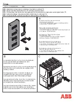
Series Intelligent Universal Circuit Breaker
A
Primary power distribution
I. Overview
The HYW3 Series Intelligent Universal Circuit Breaker (hereinafter referred to as “the circuit
breaker”) is suitable for distribution networks with AC 50/60 Hz, rated working voltage up to 690 V
and rated current below 6,300 A. The circuit breaker is mainly used for distribution, feeding and
power generation protection to protect circuits and power supplies from HHH load, undervoltage,
overvoltage, imbalance of current and voltage, short circuit and grounding. The circuit breaker can
also be directly used for overload, undervoltage and short-circuit protection of motors and
generators. The core component of the circuit breaker adopts the intelligent controller, which has
accurate selective protection, so as to avoid unnecessary power failure and improve the reliability,
continuity and safety of power supply. The circuit breaker is also equipped with an open
communication interface to realize telemetering, telesignaling, telecontrol and teleregulation, thus
meeting the requirements of the control center and automation system.
The circuit breaker complies with
GB/T 14048.2 and IEC 60947-2.
II. Model Description
II. Model Description
Controller type: M1: Mic1.0; M2: Mic2.0; M5: Mic5.0
Control voltage: AC 230 V, AC 400 V, DC 220 V, DC 110 V
Rated current: 200 A, 4,000 A, 6,300 A
Number of poles: Three-pole/Four-pole
Mounting mode: D: Draw-out type; F: Fixed type
Frame current: 1,600, 2,000, 2,500, 3,200, 4,000, 6,300
Breaking capacity: N: Common type; H: High breaking type
Design number
Universal Circuit Breaker
Enterprise code
III. Normal Operating Conditions
1. Ambient air temperature:
It is suitable for ambient temperature of -5°C
–+40°C, -40°C–+70°C (Mic1.0 standard) and -25°C–
+70°C (Mic2.0 multifunctional and Mic5.0 intelligent).
2. Altitude: The altitude of the installation location shall not exceed 2,000 meters.
3. Atmospheric conditions: The relative atmospheric humidity does not exceed 50% when the
maximum temperature is +40°C, and a higher relative humidity is allowed at a lower temperature.
For example, the humidity is 90% at 20°C, and special measures shall be taken for occasional
condensation due to the temperature change.
4. Contamination grade: Grade 3.
5. Installation category: The installation category of the breaker’s main circuit, undervoltage
release’s coil and primary coil of the power transformer is IV, and the other auxiliary circuits and
control circuits are III.
6. Use category: Class B.