


User Manual
This document is not allowed to
transmit without ZTE Corporation
’s
permission
©ZTE CORPORATION All rights reserved
22
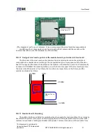
MG2639_V3 module’s output I/O level is 2.8V, therefore it needs level conversion when
connecting with standard 3.3V or 5V logic circuit
(
such as MCU or RS232 drive chip MAX3238
)
. The
most common method is to use a dynatron to realize the level conversion. Figure 4-3 shows the
level conversion to 3.3V through the UART interface of MG2639_V3. The resistance and capacitance
in figure 4-3 are just for reference, and they need to be recalculated during the design. The diode in
Figure 4-4 is Schottky diode (forward voltage drop is 0.3V). If you select other diodes, please select
one with lower forward voltage drop to make sure RXD_2V8 is below the threshold when inputting
low level.
Figure 4-4 UART interface reference design diagram
VDDIO
TXD_2V8
33.2K
1K
VCC(3.3V)
TXD_3V3
22pF
10K
RXD_3V3
100pF
RXD_2V8
VDDIO


