


9
Deviations of basic parameters
Tripping thrust
±12 % of the maximum value of the range
Adjusting speed
-10 % of the maximum value of the range
+15 % of the rated value
(in no-load operation)
Setting of signalling switches
±2.5 % of the maximum value of the range
(for the ranges, refer to the Mounting instructions).
Hysteresis of signalling switches
max. 4 % of the maximum value of the range
Setting of position-limit switches
±0.2 mm of the output pull-rod displacement
(without the influence of running-down)
Hysteresis of position-limit switches
max. 1.2 mm of the output pull-rod displacement
Clearance of output part
max. 1 mm
Protection
The actuators are fitted with one internal and one external protection terminal for ensuring protection against electric
shock injury according to ČSN 33 2000-4-41. One protection terminal is also installed on the electric motor. The protection
terminals are marked according to ČSN EN 60 417-1 and 2 (013760).
If isn´t the actuator equipment with overcurrent protection when purchased is needed to ensure that the
protection is added externally.
7. DESCRIPTION
In respect of their basic connecting dimensions, the actuators have been engineered for direct mounting to the valve.
The connection of the actuator to the valve is provided by means of columns according to ČSN 18 6314, art. 1.3, or by
means of columns and a flange
(in non-standard design
MTN, MTP 40
only).
For transmission of the output pull-rod motion of the actuator to the valve, the actuator is provided with a coupling, according to
ČSN 18 6314, Type A, art. 1.3
(with female thread),
or Type B, art. 1.3
(with male thread)
- see dimensional sketches and Tab. 2.
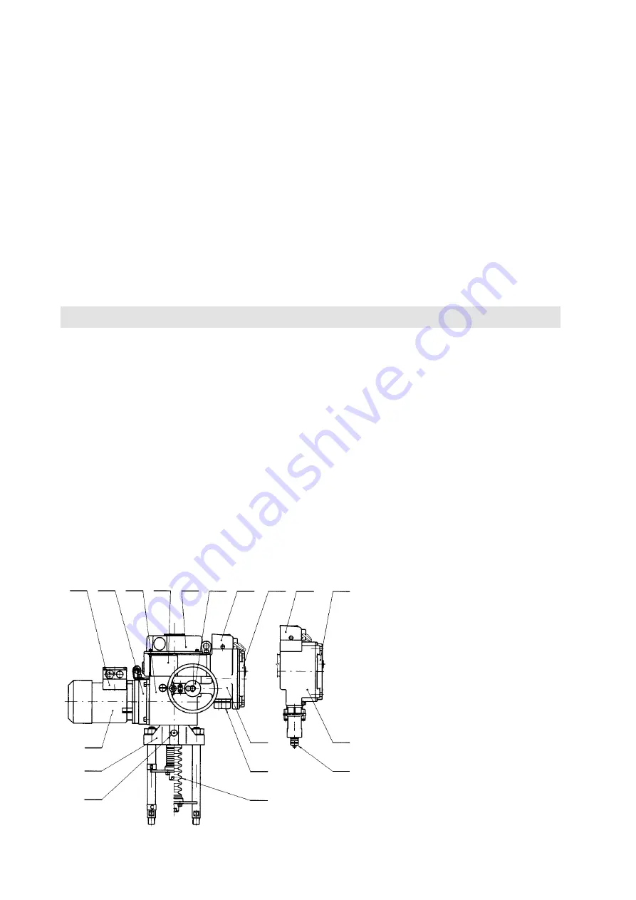
Actuator configuration (Fig.1)
The three-phase asynchronous motor 1 drives via countershaft gearing 2 the sun gear of a differential gear unit
enclosed in the supporting actuator box
(power gear transmission)
3. In the mechanical power control mode, the
crown gear of the planet differential unit is held in a steady position by a self-locking worm gear drive. The handwheel
4, which is connected with the worm, allows manual control to be accomplished even during motor operation.
The output hollow shaft is fixably coupled to the planet-gear carrier. The output shaft of the actuator is extended to
the rectilinear mechanism 11 which converts the rotary shaft motion to the rectlilinear motion of a pull-rod. The output
shaft goes into the control box 5 in which all control devices of the actuator have been concentrated, including position-
-limit, signalling and torque-limit switches, a position transmitter and the anti-condensation heater. The operation of the
position-limit and signalling switches is derived from output shaft rotation via mechanisms.
The operation of the torque-limit switches is derived from the axial displacement of a “floating worm” of the manual control unit
which is sensed and transferred to the control box by means of a lever. All controls are accessible after removal of cover 6 of the
control box. Access to the terminal box 7
(9)
is obtained after removal of cover 8. Cable inlets are secured by cable bushings 10.
Fig.1 -
Configuration of the actuator
Legend:
1 – Three–phase asynchronous motor
2 – Countershaft gear box
3 – Power transmission gear
4 – Handwheel
5 – Control box
6 – Control box cover
7 – Terminal box – design with terminal box
8 – Terminal box cover
9 – Terminal box – design with connector
10 – Cable bushings for control
11 – Rectilinear mechanism
12 – Grease cup
13 – Dust seal
14 – Terminal board of electric motor
15 – Local controller
14
2
3
5
6
4
15
8
15
8
9
10
7
10
13
12
11
1


