ZPA Pecky, a.s. 52 442 Mounting Instructions Download Page 5

5

Service life of actuators

The actuator intended for shut-off valves must be able to perform at least 10,000 operating cycles 

(C - O - C).

The actuator intended for regulating purposes must be able to perform at least 1 million cycles with operation time 

(during 

which the output shaft is moving)

 at least 250 hours. Service life in operating hours 

(h)

 depends on load and number of switching. 

Not always, high frequency of switching influences positively accuracy of regulation. For attaining the longest possible faultless 
period and service life, frequency of switching is recommended to be set to the lowest number of switching necessary for the 
given process. Orientation data of service life derived from the set regulation parameters are shown in the following table.

Service life of actuators for 1 million starts

Service life [h] 

830 

1 000 

2 000 

4 000

Number of starts [1/h] 

Max. number of starts 1200 

1 000 

500 

250

4. TECHNICAL DATA

Supply voltage 

The rated supply voltage of the actuators is 3 x 230 / 400  V,  50 Hz with permissible line voltage fluctuations between 

+10 % and -15 % and frequency shift within ±2 %. 

Protective enclosure

Protection of the actuators 

MODACT MTN (MODACT MTN Control) – IP 55 


MODACT MTP (MODACT MTP Control) – IP 67 

Noise

Acoustic pressure level A 

max. 85 dB 

(A)

Acoustic power level A 

max. 95 dB 

(A)

Tripping thrust

At  the  factory,  the  tripping  thrust  has  been  adjusted  within  the  min./max.  range  giving  in Table  1,  according  to  the 

customer’s requirements. If no tripping thrust adjustment is required the actuator is adjusted to its maximum tripping thrust.

Starting thrust

The starting thrust of the actuator is a calculated value determined by the starting torque of the electric motor and 

the total gear ratio and efficiency of the actuator. After run reversation, the actuator can produce a starting thrust for the 
duration of 1 to 2 revolutions of the output shaft when torque-limit switching is locked. This can take place in either end 
position or in any intermediate position.

Self-locking

The actuator is self-locking provided that the load only acts in the direction against motion of the actuator output shaft. 

Self-locking is ensured by a roller arrest immobilizing the electric motor rotor even in the case of manual control. 

In order to observe safety regulations, the actuators cannot be used for driving transportation lifting devices with possible 

transport of persons or for installations where persons can stand under the lifted load.

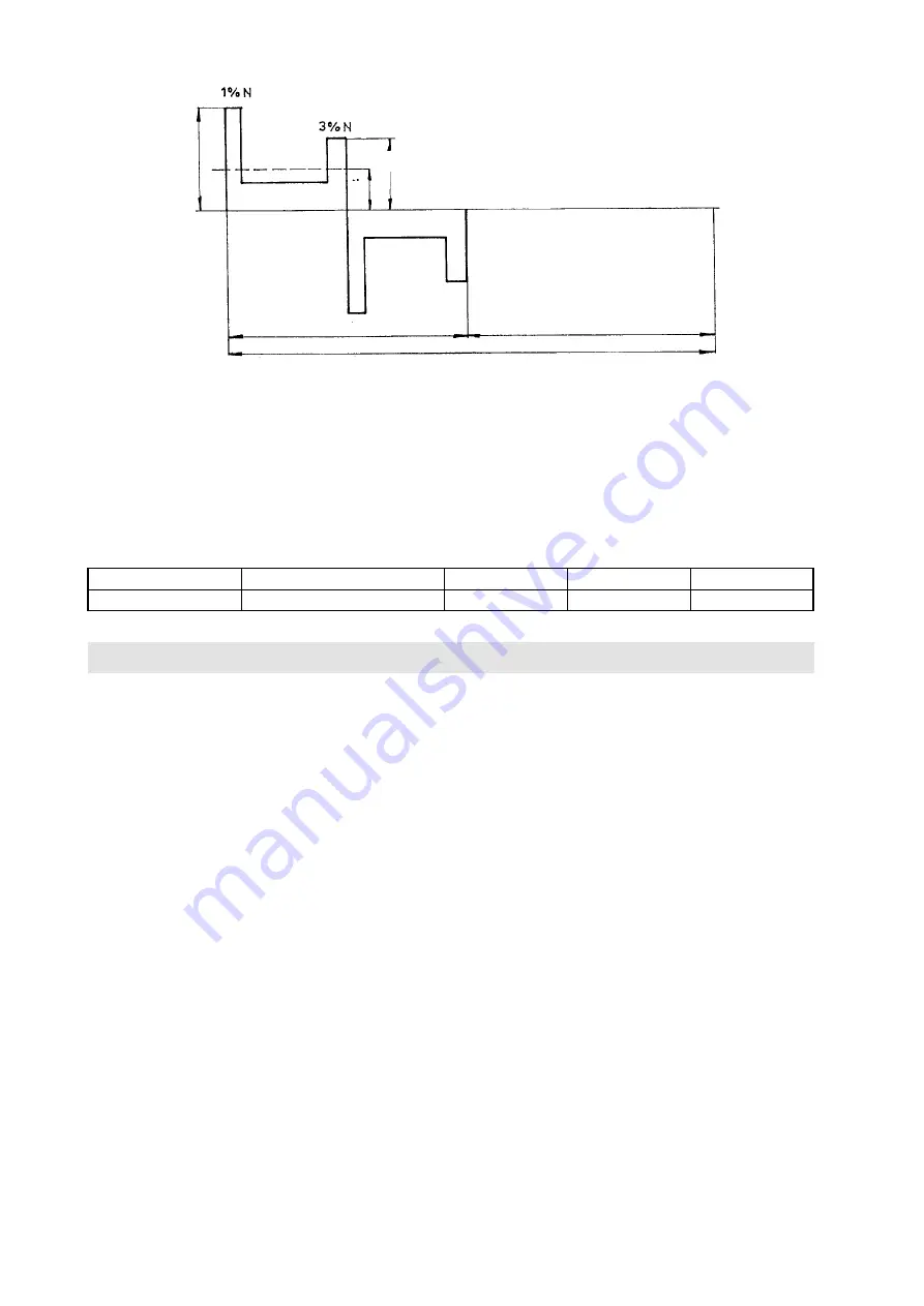
Course of working cycle

Fz  

Starting thrust ≥ 1,3 . Fv 


Fstř   Average mean load thrust 


Fv  

Maximum mean tripping thrust

F

z

F

stř

F

v

Cycle period

Operating time N

Idling time R

Summary of Contents for 52 442

Page 1: ...Type numbers 52 442 52 443 Electric Linear Pull rod actuators 4 19 MOUNTING INSTRUCTIONS...

Page 2: ...ZPA Pe ky a s is certified company in accordance with ISO 9001 as amended...

Page 3: ...tion or in the tropical atmosphere the anti condensation heater which has been built in all actuators should be always used One or two heater elements should be connected as required Installation of t...

Page 4: ...tervals The load factor N N R shall be maximum 25 per cent the longest operation cycle N R is 10 minutes The maximum number of switching actions in automatic control mode is 1200 actions per hour The...

Page 5: ...trol IP 67 Noise Acoustic pressure level A max 85 dB A Acoustic power level A max 95 dB A Tripping thrust At the factory the tripping thrust has been adjusted within the min max range giving in Table...

Page 6: ...lling switch and the SZ CLOSE signalling switch are used Each of these switches acts only in one direction of output shaft rotation The operating point of the microswitches can be set within the whole...

Page 7: ...our pole The change over switches are installed in a terminal board box and the control elements on the lid of this terminal board box Position regulator The position regulator built in in the actuato...

Page 8: ...rminals allowing conductors with a maximum cross section 4 mm2 to be connected Access to the terminal board is obtained after removal of the terminal box cover All control circuits of the electric act...

Page 9: ...e three phase asynchronous motor 1 drives via countershaft gearing 2 the sun gear of a differential gear unit enclosed in the supporting actuator box power gear transmission 3 In the mechanical power...

Page 10: ...the transmitter support is positioned at an angle of 180 C with respect to the illustrated position Fig 2a Base plate design with current transmitter 14 66 13 17 67 15 66 16 75 66 12 Legend 12 Torque...

Page 11: ...direction whereas the segment 24 is designed for the OPEN direction The torque control unit is also fitted with a locking mechanism On operation of the torque limiting switch thismechanism locks this...

Page 12: ...ranges of adjustment of the signalling switches and the transmitter are required to be changed the position of adjusting wheel K3 should be changed For this purpose the signalling unit should be parti...

Page 13: ...wheel 62 This wheel is rotated step by step by gear wheels driving cam 57 60 Turning of the cam up to the lever of the CLOSE or OPEN position limit switch PZ or PO causes the switches to change over H...

Page 14: ...ter 1 x 100 This transmitter has one sided shaft and at its end is fixed a twin wheel 73 composed of gears A and B The principle of drive and transmitter adjustment is equal as at current transmitter...

Page 15: ...rise up to the resistance value corresponding to the end position open 50 ohms until max 98 ohms Transmitter is set up by this way e Current position transmitters At the first is necessary to set up s...

Page 16: ...ssary to increase the feeding voltage within the range of recommend values or to decrease total resistance of the current loop R Caution The transmitter CPT 1Az must not be connected without checking...

Page 17: ...se Press the push button 4 then the push button 20 and keep them depressed until LED blinks When the sense of rotation is changed the end limit positions 4 mA and 20 mA remain valid but the working ra...

Page 18: ...the actuator is to be stored for a longer period than 3 years then prior to commissioning oil refilling should be made Any manipulation of the equipment at a temperature below 25 C is forbidden Storin...

Page 19: ...ng to Point 3b Caution The control box cover should be removed so that it is displaced in the direction of extended axis of the actuator output shaft taking care to avoid any damage to the position in...

Page 20: ...gap that has been thereby disclosed This procedure should be made with the pull rod in the CLOSED position 13 FAILURES AND THEIR REMOVAL Actuator in the end position does not start with motor droning...

Page 21: ...43 Figs 4 5 6 Type No 52 443 Figs 7 Position transmitter block of local control MODACT MTN MTP actuators 9th place of t no current transmitter 4 20 mA current transmitter 4 20 mA with BMO without BMO...

Page 22: ...of columns B 150 mm Character on 7th place Ba1I Ba1II Ba1III Ba2I Ba2II Ba2III Bb1I Bb1II Bb1III Bb2I Bb2II Bb2III Bg2I C D E F G H I J K L M P R Spacing of columns Position Closed Thread of coupling...

Page 23: ...f b ch g e a f b ch g e a 40 a b g a b g max 38 253 max 595 261 max 334 153 100 25 c a d b h g d b h g c a Design 1 M 20 M 20 297 26 A B A B Design 2 Detail of coupling M 20 x 1 5 I M 16 x 1 5 II M 10...

Page 24: ...g 130 c a 308 d b 352 h g 408 e a 633 f b 677 ch g 733 max 595 max 334 261 325 e a c a d b h g 253 100 153 a b g M20 26 f b ch g 25 215 99 90 e a c a d b h g f b ch g a b g 40 M20 A B Design 1 Detail...

Page 25: ...ype No 52 443 x1xxx Fig 5 697 436 M30x2 M30 160 261 350 257 835 36 48 60 120 485 376 120 200 with block of terminals with connector External protectivet erminal Local control 697 436 M30x2 M30 160 261...

Page 26: ...on unit for MODACT MTN MTP 40 electric actuators Type No 52 443 x2xxx design with flange non standard other dimensions and designs of actuators are according to fig 14 15 16 215 160 4x 13 80H8 105 0 2...

Page 27: ...Q1 MO OPEN torque limit switch SQ2 MZ CLOSE torque limit switch SQ3 PO OPEN position limit switch SQ5 PZ CLOSE position limit switch SQ4 SO OPEN signalling switch SQ6 SZ CLOSE signalling switch SA1 LO...

Page 28: ...ervomotor MODACT MON MOP Control se styka i a BMO se svorkovnic Wiring diagram of MODACT MTN MTP Control electric actuators with contactors with terminal board P3 0947 Outlet position Control phase BA...

Page 29: ...servomotor MODACT MON MOP Control se styka i a regul torem ZP2 RE5 se svorkovnic Zapojen elektrick ch servomotor MODACT MON MOP Control se styka i regul torem ZP2 RE5 a BM se svorkovnic with terminal...

Page 30: ...jumper into clamps t1 t2 Control signal 0 4 20 mA Outlet Position 3 phase motor Brake BR2 blue blue brown brown BRAKE Connect surge voltage protectors to contactor coils O C L R Zapojen elektrick ch s...

Page 31: ...orem Zapojen elektrick ch servomotor MODACT MON MOP Control se styka i a BMO s konektorem P3 0953 P3M 0954 SA2 O C SA1 L R Wiring diagram of MODACT MTN MTP Control electric actuators with contactors O...

Page 32: ...iagram of MODACT MTN MTP Control electric actuators with contactors and ZP2 RE5 regulator Wiring diagram of MODACT MTN MTP Control electric actuators with contactors ZP2 RE5 regulator and BMO with con...

Page 33: ...the control box Sealing ring 60x50 PN 02 9280 2 1 Sealing of output shaft in the control box cover Sealing ring 190x3 PN 02 9281 0 Sealing of control box cover Potentiometer 2 x 100 2340510232 1 Moun...

Page 34: ...34 NOTES...

Page 35: ...ary multi turn actuators MODACT MO EEx MOED EEx Explosion proof electric multi turn actuators MODACT MOA Electric multi turn actuators for nuclear power stations application outside containment MODACT...

Page 36: ...tel 420 321 785 141 9 fax 420 321 785 165 420 321 785 167 e mail zpa zpa pecky cz ZPA Pe ky a s t 5 kv tna 166 289 11 PE KY Czech Republic www zpa pecky cz...

Reviews: