background image

11

© Copyright 2017 Zoeller

®

 Co. All rights reserved.

Cutter Maintenance

1. 

All power circuits must be disconnected and locked out 

before any attempts are made at servicing.

 The cutter and 

disc can be removed and sharpened by grinding the cutting 

faces. Both cutter and disc must be removed from the pump. 

Removal of these parts can be accomplished in the field by 

removing pump from the sump and positioning horizontally 

to access the intake of the pump. If seals or other repairs are 

required, the pump must be totally removed and serviced in 

a shop by a qualified pump technician or authorized service 

center.

2.  Remove the three countersunk screws on the ring.

3.  Thoroughly clean the cutter and disc assembly. Tilt pump 

back to the vertical position to make certain the end play has 

been removed. Check and record the clearance between 

the cutter and disc with a feeler gage. The correct running 

clearance is between 0.004" and 0.008".

4.  With pump in horizontal position, heat the hex head bolt in 

the center of the cutter with a propane torch. The bolt must 

be heated to 350° F to soften the thread lock sealer on the 

bolt for ease of removal. Remove the bolt by turning in a 

counterclockwise rotation. It will be necessary to use a wood 

block to prevent the cutter from turning while removing the 

bolt. Pull cutter from the shaft and remove the spacer shims 

located behind the cutter.

5.  Remove the six cap screws holding the disc and remove disc 

from the pump.

6.  The disc and cutter can be replaced with new service parts 

or resurfaced by grinding. Resurfacing is accomplished by 

surface grinding both disc and cutter to a 32 micro finish. Do 

not attempt grinding in the field. Send parts to a qualified 

machine shop or return to the factory for repair. The disc, 

cutter and shims are a matched set. Keep parts together. 

Measure disc before and after resurfacing with micrometer 

and record measurements.

  7.  After resurfacing, the disc and cutter must be flat within 0.001". 

If the disc has been surface ground, it will be necessary to 

remove shims to compensate for the material removed from 

the disc.  As a starting point, remove shims of the same thick-

ness as the amount  machined from the cutter disc (step 6 

above).  Final running clearance must be between 0.004” 

and 0.008”.  Be sure pump is in vertical position and all end 

play has been removed before measuring.

  8. Clean bottom of pump where disc is located and replace 

disc and retainer screws. Torque to 63-67 in-lbs.  Replace 

cutter with the correct shims. Install washer and torque hex 

head bolt to 71-75 in.-lbs. Apply Loctite 262 thread-lock 

sealant or equal to bolt threads prior to insertion. Check 

running clearance with pump in vertical position to remove 

end play. Clearance must be between 0.004" and 0.008" to 

obtain efficient grinding when pump is put back in service.

  9.  Replace six cap screws.

10.  Check the oil in the motor housing before reinstalling. Contact 

the factory if the oil has a milky appearance or burnt smell. 

The level should be even with the fill plug when pump is in 

the upright position. Add oil if required. Use insulating oil 

supplied by the factory.
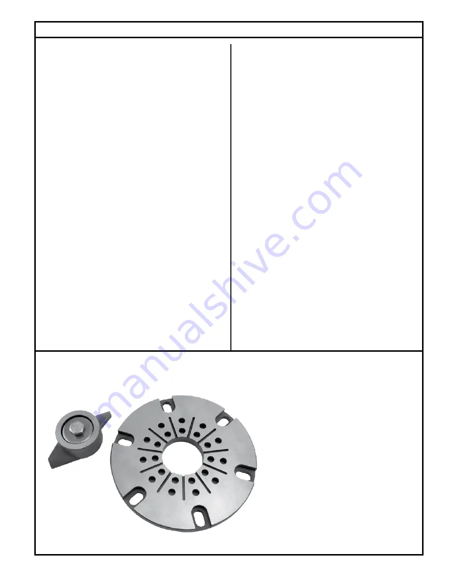
FIGURE 6.

To remove cutter:  Heat the center bolt to 350°F 

to loosen Loctite

®

 thread sealant.

Grind the Cutter and Disc seen here to a 32 

microfinish.  Surfaces must be flat to within 0.001" 

T.I.R.  Gap must be between 0.007" and 0.012" on 

these parts.

Summary of Contents for SHARK 818 Series

Page 1: ...ntents Safety Instructions 1 Limited Warranty 2 Preinstallation Checklist 3 General Information 4 Pump Wiring Instructions 5 Typical Indoor Prepackaged System 6 Indoor Prepackaged Installation Instructions 7 Typical Outdoor Prepackaged System 8 Outdoor Prepackaged Installation Instructions 9 Operation 10 Cutter Maintenance 11 Service Checklist 12 Safety Instructions TO AVOID SERIOUS OR FATAL PERSO...

Page 2: ... user or 18 months from date of original manufacture of the product whichever comes first Parts that fail within the warranty period one year from date of purchase by the end user or 18 months from the date of original manufacture of the product whichever comes first that inspections determine to be defective in material or workmanship will be repaired replaced or remanufactured at Manufacturer s ...

Page 3: ... grinder pump or other pit peculiarities and are secured so that the grinder pump will shut off It is recommended to use rigid pipe and fittings and the pit be 24 in diameter for simplex systems and 36 in diameter for duplex systems or larger 4 Grinder installations should be checked yearly for debris and or build up which may interfere with the ON or OFF positions of variable level float controls...

Page 4: ...ust comply with the National Electrical Code and applicable local codes Conduit and panel enclosure openings must have a gas and watertight seal Installation of electrical panels conduit and connections should be made by a qualified licensed electrician A UL Listed potting kit P N 10 2350 is available from Zoeller Company 4 When installing a pump with a check valve or a rail system with a check va...

Page 5: ...iagram above to secure the float switch properly and obtain the proper tether to customize the on off cycle to each application Note the minimum off level shown above On Prepackaged Systems the tether length is set at 5 Determining Pumping Range in Inches 1 inch 2 5 cm Tether Length 5 10 15 20 22 Pumping Range 9 13 5 18 22 24 Use only as a guide Due to weight of cable pumping range above horizonta...

Page 6: ...4 STEEL CORD SEAL INSPECTION PLATE 3 GROMMET SEAL SWITCH CORD ALARM FLOAT BASIN COVER LIFTING BOLT 16 X 1 4 STEEL 5 16 304 STAINLESS STEEL PUMP PLATE PUMP POWER CORD SILENCE INPUT 1 POWER ON FIELD INSTALLED ALARM 4 RUBBER INLET CAST IRON ADAPTERS OFF 24 NOMINAL TO ALARM PANEL BALL VALVE FIELD INSTALLED GALVANIZED PIPE 1 1 4 X 32 GALVANIZED PIPE 1 1 4 X 12 GRINDER PUMP SINGLE PHASE 2HP 1 1 4 GROMME...

Page 7: ...n a very low traffic area within 15 of the power disconnect The hole should be at least 8 larger in diameter than the basin in order to leave 4 of backfill all the way around the perimeter A minimum of 4 of compacted subbase is also required Backfill and subbase should be 1 8 to 3 4 pea gravel or 1 8 to 1 2 crushed stone Also reference the basin installation instructions included with the unit 6 T...

Page 8: ... AFD 1 25 2 Z RAIL 2 CAST IRON CHECK VALVE 3 4 GALV GUIDE RAILS 2 SCH 80 BALL VALVE 2 FLEX BOOT FITTING LOCATION VARIES WITH BASIN DEPTH FLOAT TREE ASSEMBLY 2HP GRINDER PUMP 2 PVC SCH 80 PLBG 1 8 302 STAINLESS STEEL LIFTING CABLE ALARM ON OFF SOLID FIBERGLASS COVER HIGH WATER ALARM OR SIMPLEX CONTROL PANEL FIELD INSTALLED ALARM FLOAT SWITCH MUST OPERATE OFF LOW VOLTAGE TO BE USED WITH QWIK BOX SK3...

Page 9: ...iameter with the hole in the basin Attach the hub to the side of the basin using the sealant and hardware provided 6 The bottom of the excavation can now be properly backfilled compactedandleveled Setbasininhole Ensuretheremovable cover extends above the finished grade line and the grade slopes awayfromtheunit Backfillandsubbaseshouldbe1 8 3 4 pea gravel or 1 8 1 2 crushed stone Reference basin in...

Page 10: ...nd securely installed Floats positioned properly Discharge valves open 3 16 vent hole drilled in pipe between check valve and pump Once the above has been verified proceed with the following checks Pump power cables and control floats properly installed and voltage verified Conduit connections to panel and junction box are properly sealed After installing the pump into the containment area with ad...

Page 11: ...by surface grinding both disc and cutter to a 32 micro finish Do not attempt grinding in the field Send parts to a qualified machine shop or return to the factory for repair The disc cutter and shims are a matched set Keep parts together Measure disc before and after resurfacing with micrometer and record measurements 7 Afterresurfacing thediscandcuttermustbeflatwithin0 001 If the disc has been su...

Page 12: ... always disconnect pump and panel from its power source before handling Neverenterthebasinuntilithasbeenproperlyvented and tested Any person entering a basin should be wearing a harness with safety rope extending to the surface so that they can be pulled out in case of asphyxiation Sewage water gives off methane and hydrogen sulfide gases both of which can be highly poisonous Installationandchecki...

Reviews: