


3
© Copyright 2008 Zoeller Co. All rights reserved.
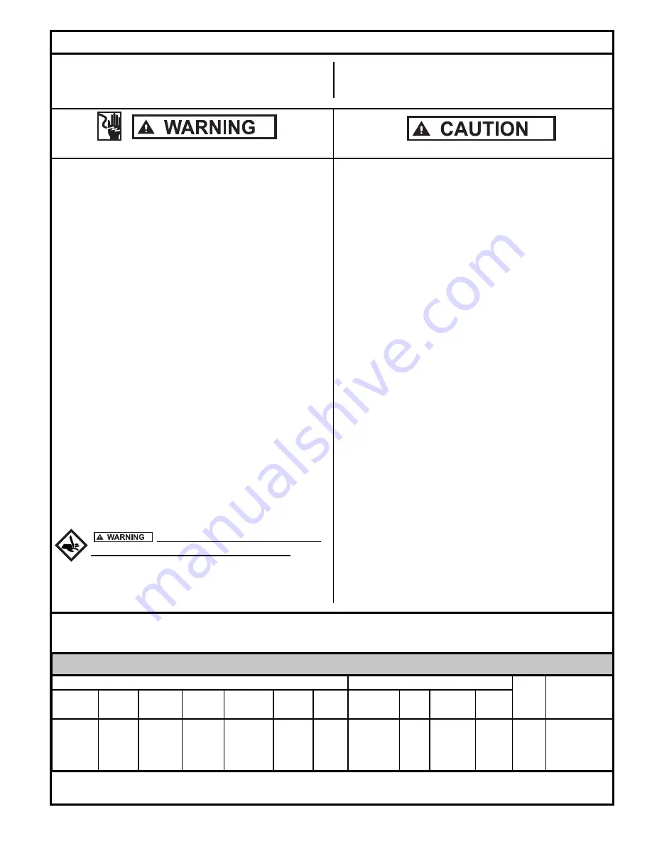
Preinstallation Checklist
1.
Inspect your grinder pump.
If the unit has been damaged in
shipment, contact your dealer before installing.
Do Not
remove
the test plug in the cover nor the motor housing.
2.
Carefully read all literature
to familiarize yourself with details
re gard ing in stal la tion and use. Retain materials for future
reference.
1.
Make sure pump connection con tains a ground ter mi nal.
The power cord on all Zoeller Grind er Pumps con tains a green
con duc tor for grounding to help protect you against the pos si bil i ty
of electric shock.
2.
Make certain the receptacle is within reach of the power
supply cord
.
3.
Make sure any panels and branch circuits are equipped
with
proper size fuses and circuit break ers. An in de pen dent pow er
circuit is rec om mend ed, sized ac cord ing to the National Elec tri cal
Code, for the current shown on the grinder pump name plate.
4.
Automatic pumps have three prong plug caps and must
be connected to a three prong grounded re cep ta cle with
ground fault circuit interrupter (GFCI).
5.
For your protection, always dis con nect the pow er source to
the grinder pump before han dling.
All grinder pumps must be
prop er ly ground ed and wired in ac cor dance with the “Na tion al
Elec tri cal Codes” and all local codes and ordinances.
6. Installation of electrical hardware and checking of control pan-
els and circuits should be performed by a quali
fi
ed li censed
electrician.
7. Risk of electrical shock - These pumps have not been in ves ti gat ed
for use in swimming pool areas.
8. According to the state of California (Prop 65), this product
contains chemicals known to the state of California to cause
can cer and birth defects or other reproductive harm.
1.
Make sure the power source
is capable of handling the
electrical re quire ments of the grinder pump, as indicated on
the nameplate.
2.
A dis con nect switch should be installed ahead of the
pump.
3. If Grinder pumps are operated by control panels with vari-
able level
fl
oat control switches, it is the re spon si bil i ty of the
in stall ing party that
fl
oat control switches will not hang up on
the grinder pump or other pit peculiarities and are secured so
that the grinder pump will shut off. It is recommended to use
rigid pipe and
fi
ttings and the pit be 24" in diameter for simplex
sys tems and 36" in di am e ter for duplex systems or larger.
4. Grinder installations should be checked yearly for debris and/or
build up which may interfere with the “ON” or “OFF” positions of
variable lev el
fl
oat control switches. Repair and service, other
than cutter as sem bly main te nance, should be per formed by
Zoeller au tho rized service stations only.
5. Maximum operating tem per a ture must not ex ceed 130°F,
(54°C).
6.
Pump and
fl
oat switch electrical connections must be
permanently installed, operational and protected from
submergence.
7.
Junction box conduit must be installed with watertight
connection. Zoeller junction boxes include a UL Listed
potting kit for sealing conduit. Failure to properly install
this sealant material could void warranty.
SEE BELOW FOR LIST OF WARNINGS
SEE BELOW FOR LIST OF CAUTIONS
Electrical Data
Amps Winding
Locked
KVA
Resistance
Model
BHP
Mode
RPM
Voltage Phase Hertz Full Load In Air Shut Off Rotor Code Line-to-Line
WD820 2 Auto 3450 230 1 60 13.7 7.6
10.2 57 H 1.2
/
2.0
E820 2 Nonauto
3450 230 1 60 13.7 7.6
10.2 57 H 1.2
/
2.0
WH820
2
Auto
3450
200
1
60
15.5
8.8
11.0
61.6
H
.8 / 2.0
I820
2
Nonauto
3450
200
1
60
15.5
8.8
11.0
61.6
H
.8 / 2.0
Do not attempt to turn star cutter
located on bottom of the unit with
fi
ngers.
Use a
wrench when check ing or re mov ing star cutter.


