background image

11

© Copyright 2008 Zoeller Co. All rights reserved.

Cutter Maintenance

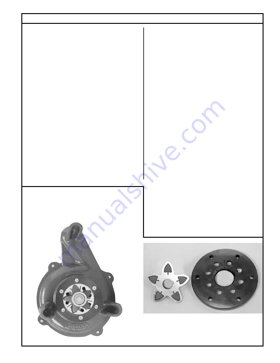
To remove star cutter:  Remove guard ring then heat the 

cen ter bolt to 350°F to loos en Loctite® thread seal ant.

Grind the Star Cutter and Disc seen here to a 32 micro

fi

 nish.  

Sur fac es  must  be 

fl

 at to within 0.001” T.I.R.  Gap must be be tween 

0.004” and 0.008” on these parts.

1. 

All power circuits must be dis con nect ed and locked 

out before any attempts are made at servicing.

 The star 

cutter and disc can be removed and sharp ened by grinding 

the cut ting faces. Both star cutter and disc must be re moved 

from the pump. Removal of these parts can be ac com plished 

in the 

fi

 eld by removing pump from the sump and po si tion ing 

hor i zon tal ly to access the intake of the pump. If seals or other 

repairs are required, the pump must be totally removed and 

serviced in a shop by a quali

fi

 ed pump technician or au tho rized 

service center.

2.  Remove the three countersunk screws on the plastic guard 

ring and remove the ring.

3.  Thoroughly clean the star cutter and disc assembly. Tilt pump 

back to the vertical po si tion to make certain the end play has 

been removed. Check and record the clearance be tween the 

star cutter and disc with a feeler gage. The correct running 

clear ance is between 0.004" and 0.008".

4.  With pump in horizontal position, heat the hex head bolt in 

the center of the star cutter with a propane torch. The bolt 

must be heated to 350°F to soften the thread lock sealer on 

the bolt for ease of removal. Remove the bolt by turning in a 

coun ter clock wise rotation. It will be necessary to use a wood 

block to prevent the star cutter from turning while re mov ing 

the bolt. Pull star cutter from the shaft and remove the spacer 

shims located behind the star cutter.

5.  Remove the three cap screws holding the disc and remove 

disc from the pump.

6.  The disc and star cutter can be replaced with new service 

parts or resurfaced by grinding. Re sur fac ing is ac com plished 

by surface grinding both disc and star cutter to a 32 micro 

fi

 nish. Do not attempt grinding in the 

fi

 eld. Send parts to a 

quali

fi

 ed machine shop or return to the factory for repair. The 

disc, star cutter and shims are a matched set. Keep parts 

together. Measure disc before and after re sur fac ing with 

micrometer and record measurements.

  7.  After resurfacing, the disc and star cutter must be 

fl

 at within 

0.001". If the disc has been surface ground, it will be neces-

sary to remove shims to com pen sate for the ma te ri al removed 

from the disc.  As a starting point, remove shims of the same 

thickness as the amount  machined from the cutter disc (step 

6 above).  Final running clearance must be between 0.004” 

and 0.008”.  Be sure pump is in vertical position and all end 

play has been removed before mea sur ing.

  8.  Clean bottom of pump where disc is located and replace 

disc and retainer screws. Torque to 63-67 in-lbs.  Replace 

star cutter with the correct shims. Install washer and torque 

hex head bolt to 71-75 in.-lbs. Apply Loctite 262 thread-lock 

sealant or equal to bolt threads prior to insertion. Check 

running clearance with pump in vertical po si tion to re move 

end play. Clear ance must be between 0.004" and 0.008" to 

obtain ef

fi

 cient grinding when pump is put back in service.

  9.  Replace plastic guard ring and its three screws.

10.  Check the oil in the motor housing before reinstalling. Con tact 

the factory if the oil has a milky appearance or burnt smell. 

The level should be even with the 

fi

 ll plug when pump is in 

the upright position. Add oil if re quired. Use insulating oil 

sup plied by the factory.

FIGURE 6.

Summary of Contents for 820

Page 1: ...n Table of Contents Safety Instructions 1 Limited Warranty 2 Preinstallation Checklist 3 General Information 4 Pump Wiring Instructions 5 Typical Indoor Prepackaged System 6 Indoor Prepackaged Installation Instructions 7 Typical Outdoor Prepackaged System 8 Outdoor Prepackaged Installation Instructions 9 Operation 10 Cutter Maintenance 11 Service Checklist 12 Safety Instructions TO AVOID SERIOUS O...

Page 2: ...equential damages so the above limitation or exclusion may not apply to you This warranty gives you specific legal rights and you may also have other rights which vary from state to state Manufacturer warrants to the purchaser and subsequent owner during the warranty period every new product to be free from defects in material and workmanship under normal use and service when properly used and mai...

Page 3: ...1 Make sure the power source is capable of handling the electrical requirements of the grinder pump as indicated on the nameplate 2 A disconnect switch should be installed ahead of the pump 3 If Grinder pumps are operated by control panels with vari able level float control switches it is the responsibility of the installing party that float control switches will not hang up on the grinder pump or...

Page 4: ... system installation 3 All electrical connections including pump to control box and power supply to control panels must comply with the National Electrical Code and applicable local codes Conduit and panel enclosure openings must have a gas and watertight seal Installation of electrical panels conduit and connections should be made by a qualified licensed electrician A UL Listed potting kit P N 10...

Page 5: ...duit directly to pump Pump Wiring Instructions Installation and checking of electrical circuits and hardware should be performed by a qualified licensed electrician 010415 AUTOMATIC WIRING DIAGRAM MODELS WD820 and WH820 010443 NONAUTOMATIC WIRING DIAGRAM MODELS E820 and I820 FIGURE 4 FIGURE 5 Models WD WH are fully automatic A float switch is included and factory wired in the pump circuit to provi...

Page 6: ...0 X 1 4 STEEL CORD SEAL INSPECTION PLATE 3 GROMMET SEAL SWITCH CORD ALARM FLOAT BASIN COVER LIFTING BOLT 16 X 1 4 STEEL 5 16 304 STAINLESS STEEL PUMP PLATE PUMP POWER CORD ON FIELD INSTALLED ALARM 4 FIBERGLASS HUB CAST IRON ADAPTERS OFF 24 NOMINAL TO ALARM PANEL BALL VALVE FIELD INSTALLED GALVANIZED PIPE 1 1 4 X 32 GALVANIZED PIPE 1 1 4 X 12 GRINDER PUMP SINGLE PHASE 2HP 1 1 4 GROMMET SEAL FIELD I...

Page 7: ...very low traffic area within 15 of the power disconnect The hole should be at least 8 larger in diameter than the basin in order to leave 4 of backfill all the way around the perimeter A minimum of 4 of compacted subbase is also required Backfill and subbase should be 1 8 to 3 4 pea gravel or 1 8 to 1 2 crushed stone Also reference the basin installation instructions included with the unit 6 The 4...

Page 8: ...EL PULL ROD 3 8 X 1 416 STAINLESS ALARM FLOAT HIGH LEVEL DISCHARGE FITTING 1 1 4 BULK HEAD FIELD INSTALLED 4 RUBBER INLET PIPE SEAL 28 MIN OR PER STATE AND LOCAL CODES COUPLING TO CONTROL PANEL HIGH WATER ALARM FIELD INSTALLED 60 OTHER BASIN SIZES ARE READILY AVAILABLE Typical Outdoor Grinder Pumping System Installation All installations must comply with all applicable electrical and plumbing code...

Page 9: ...lant and hardware provided 6 The bottom of the excavation can now be properly backfilled compacted and leveled Set basin in hole Ensure the removable cover extends above the finished grade line and the grade slopes away from the unit Backfill and subbase should be 1 8 3 4 pea gravel or 1 8 1 2 crushed stone Reference basin installation instructions included with unit Connect the 4 inlet pipe to th...

Page 10: ...nd securely installed Floats positioned properly Discharge valves open 3 16 vent hole drilled in pipe between check valve and pump Once the above has been verified proceed with the following checks Pump power cables and control floats properly installed and voltage verified Conduit connections to panel and junction box are properly sealed After installing the pump into the containment area with ad...

Page 11: ...vethespacer shims located behind the star cutter 5 Remove the three cap screws holding the disc and remove disc from the pump 6 The disc and star cutter can be replaced with new service partsorresurfacedbygrinding Resurfacingisaccomplished by surface grinding both disc and star cutter to a 32 micro finish Do not attempt grinding in the field Send parts to a qualified machine shop or return to the ...

Page 12: ...t system for proper operations Repair and service should be performed by a Zoeller Pump Company Authorized Service Station only SAFETY PROCEDURES For your protection always disconnect pump and panel from its power source before handling Never enter the basin until it has been properly vented and tested Any person entering a basin should be wear ing a harness with safety rope extending to the surfa...

Reviews: