background image

Page 9

2.10.1 Remote Closure 4 Application - 

Booster Pump Support

The behavior of remote closure 4 may be 

used to allow an external timeclock fitted with a 
20-minute electrical isolation switch (e.g., Intermatic 
P/N 156T4042A) to properly control the ePump™ in 
conjunction with a booster pump.
Connection for Booster Pump Support:

1. 

Turn off all switches and the main breaker that 
supplies power to the ePump™.

  WARNING

ELECTRICAL SHOCK HAZARD

Turn off all switches and the main breaker in the ePump™ 
electrical circuit before starting the procedure. Failure to 
comply may cause a shock hazard resulting in severe 
personal injury or death.

2. 

Install the normally-closed electrical isolation 
switch to the timeclock assembly. (See 
timeclock manufacturer’s instructions for 
details.)

3. 

Connect the main timeclock contacts to the 
booster pump power input per the booster pump 
installation manual.

4. 

Connect one side of the fireman’s switch 
to the ePump™ Controller at J3 REMOTE 
CONTROL, COMMON.

5. 

Connect the other side of the fireman’s switch 
to the ePump™ controller at J3 REMOTE 
CONTROL, INPUT 4.

6. 

Set the timeclock to the desired on/off times.

7. 

Turn on all switches and the main breaker 
feeding power to the ePump™.

If the installation is working properly, the 
fireman’s switch will open 20 minutes before 
the booster pump shuts down, the ePump™ 
will continue to run for 30 minutes, and the 
ePump™ Controller will display 

PUMP WILL 

REMAIN ON FOR xx:xx

, where 

xx:xx

 is the 

time remaining until ePump™ shutdown.

Section 3. Overview of the Controller

3.1 

The ePump™ Controller

The ePump™ controller contains an advanced 

microcontroller that provides a simple yet sophisticated 
interface to operate your ePump™ for maximum 
efficiency and enjoyment of your pool.

The controller allows operation of the ePump™ 

in three ways: Manually, from built-in timers, and 
remotely via contact closures.
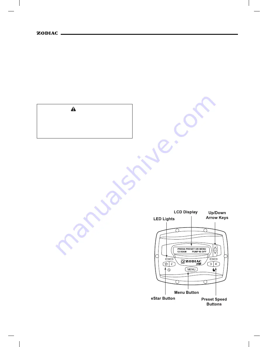
3.2 

The ePump™ Controller Interface

The ePump™ controller interface panel 

provides both timed and manual speed controls for the 
ePump™. 

Four (4) speed presets are directly available on 

the panel, while four additional presets may be accessed 
via the 

MENU

 key. 

The up and down arrow keys are used to adjust 

the pump speed. Speed is saved as it is adjusted. No 
further action is required to save the new speed setting 
after adjustment. The selected speed can be saved and 
assigned to one of the speed buttons.

As shown below, preset speed "

" is assigned 

to the eStar feature. Hence, it is intended to be assigned 
an energy-efficient filtration speed, as determined by the 
installer.

Summary of Contents for ePump

Page 1: ...t must be installed and serviced by a professional pool spa service technician The procedures in this manual must be followed exactly Failure to follow warning notices and instructions may result in p...

Page 2: ......

Page 3: ...r 9 3 1 The ePump Controller 9 3 2 The ePump Controller Interface 9 3 3 Basic Functions 10 Section 4 User Operation 10 4 1 OFF Mode 10 4 2 RUN Mode 10 4 3 Manual Start and Stop 10 4 4 Pump Speed Setti...

Page 4: ...en or missing Never replace a suction fitting with one rated less than the flow rate marked on the equipment assembly WARNING To Reduce the Risk of Injury a The water in a spa should never exceed 40 C...

Page 5: ...mometer Do not use a spa or hot tub immediately following strenuous exercise Prolonged immersion in a spa or hot tub may be injurious to your health Do not permit any electric appliance such as a ligh...

Page 6: ...r Components The ePump controller assembly See Figure 2 contains the following components 1 ePump Controller 2 Mounting Gasket 3 Backplate 4 Round Seal 5 Six 6 Screws Additional materials are required...

Page 7: ...igure 2 5 Mark the hole locations on the wall and use the fastener to secure the backplate to the wall 6 At the bottom of the backplate cut the two 2 tabs out with an appropriate tool such as a Stanle...

Page 8: ...n on all switches and the main breaker feeding power to the ePump 5 Verify the operation of the contact closures If the correct speed is activated when the closure is activated the ePump starts and th...

Page 9: ...in breaker feeding power to the ePump 8 If the installation is working properly the fireman s switch will open 20 minutes before the booster pump shuts down the ePump will continue to run for 30 minut...

Page 10: ...time of day clock 4 2 RUN Mode When the pump is running not off the controller displays n label 00 00 RPM xxxx where n label is the number and label of the selected preset 00 00 is the time of day clo...

Page 11: ...e only within a certain range The minimum and maximum limits of the range are set by the installer 4 5 Timeclock Setup and Operation The controller allows the user to create timed pump programs on pum...

Page 12: ...hen starting the pump via a timed program the pump will first run at the priming speed for the priming duration as set by the installer If a program overlap occurs the pump will immediately start at t...

Page 13: ...ller for further information 4 7 Pump Freeze Protect To help protect against pump damage the controller monitors the temperature inside the pump If enabled pump freeze protect will start the pump at t...

Page 14: ...Minimum and maximum pump speeds eStar speed Pump Freeze Protect operation 5 1 Entering Service Setup NOTE The ePump controller must be in the OFF mode all LED s lights must be off before entering the...

Page 15: ...To clear the fault history press either arrow key 5 5 Priming Speed and Duration The ePump controller will command the ePump to operate at the priming speed for the priming duration specified except d...

Page 16: ...protect equipment and plumbing for short periods of freezing only It does this by activating the filtration pump and circulating the water to prevent freeze inside equipment or plumbing Freeze protec...

Page 17: ...SET Press the MENU button to display the currently selected preset Using the arrow keys choose the preset to be changed Press MENU to select The controller displays SELECT LABEL TYPE Select GENERAL or...

Page 18: ...election From the setup menu select LANGUAGE using the arrow keys Press MENU Using the arrow keys select the desired language Press MENU to save the selection 6 7 Run Duration Presets 3 and 4 Only Pre...

Page 19: ...Page 19 Section 7 Menu Flow Chart...

Page 20: ...H0352000 Zodiac Group Australia Pty Ltd 219 Woodpark Road Smithfield NSW 2164 Ph 1800 688 552 Fax 02 9756 3987...

Reviews: