background image

P-15

P-16

Installation instructions

Step-by-step installation instructions 
(rear entry wiring)

Step


3

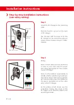
Use  the  4pcs  M6*8  screws  to  fix  the 
EV  charger  to  the  mounting  plate  as 
picture shows (Screws torque 1.5NM-
2.0NM).

 
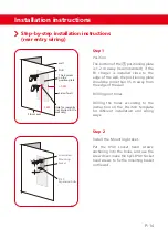
Find the hole for cut out on the back 
of EV charger.

lnstall the EV Charger to the


mounting 

plate.

Step


4

Note: lt is the installer's responsibility to 
identify whether additional grounding is 
required to ensure that local regulations 
are met.Grounding must be installed at 
the  power  sourceand  not  at  the  cable 
entry to the EV Charger.

As  the  picture  at  left  shows,  use  the 
screwdriver  loosing  the  screws  on  the 
EV charger cover. Wire the cable to the 
according terminal.

Note: Consult with your local electrician 
or  refer  to  your  local  code  for  proper 
wire  sizing  appropriate  for  the  currents 
in your EV Charger.

Wiring

Left hole position

Right hole
position

Back of EV charger

perforating

as image

M6

*

8 bolts

cable through the hole 

on the wall and 

connect to the back 

hole of EV

Wiring teminals


Three

-

phase 

wiring diagram

Installation instructions

Do  not  connect  the  power  cord  before  reading  and  fully  understanding  all  the 
concepts  introduced  in  this  section.  If  you  are  not  sure  whether  the  type  of  power 
supply on the repair panel is available, please consult an electrician for assistance.

Be careful of electric shock! Before use, use a voltmeter to confirm that there is no 
voltage on the power supply line or terminal to ensure that the power has been cut 
off.

Warning

Reinstall the sealing cover and
Turn on power

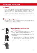
②. 

After sealing cover fixing, put the facia on and fix it on the 

sealing cover. 

④. 

Recommend to install a circuit breaker 40A/2P 30MA.

① . 

Use  a  screwdriver  to  lightly  secure  the  sealing  cover  by 

installing only the top screws at 

(

1.5NM-2.0NM )torque.

③ . 

If  you  need  to  open  the  front  cover,  change  the  internal 

settings,  please  use  the 

plastic  lifter  to  unclench  along  the 

edge of the cover.

Set the operating current

After installation, users can set the maximum operating current of the EV charger in 
the APP, Please refer to APP manual for details.

Summary of Contents for BCP Series

Page 1: ...BCP Series AC EV Charger Use and lnstallation Manual Scan For More Information ...

Page 2: ...G R E E N S M A R T ...

Page 3: ... safety instructions Cautions Notes Specification Features P 01 P 02 P 02 P 03 P 03 Maintenance instructions Product overhaul Warranty description Safety notice Operation and maintenance risk notification Use risk notification P 20 P 20 P 21 P 21 In the box In the box P 09 Installation lnstructions Step by step installation instructions bottom entry wiring Step by step installation instructions to...

Page 4: ...Charger The EV Charger is not user serviceable Contact us for any repairs or modification Do not touch the EV Charger s end terminals with sharp metallic objects such as wire tools or needles Read this entire mandatory document before installing or using the EV charger This device should be supervised when used around children Transporting the EV Charger handle with care Do not subject it to stron...

Page 5: ...Charger itself Any resulting damage is excluded from New Vehicle Limited Warranty and the EV Charger Limited Warranty Do not use private power generators as a power source for charging Do not operate the EV Charger in temperatures outside its operating range of 25 to 55 That cord extension sets are not allowed to be used Notes Ensure that the EV Charger s charging cable is positioned so it will no...

Page 6: ...t protection over temperature protection imperfect earth detection CP abnormal signal protection and type A DC 6mA for europe standard IP65 Socket IP55 protecting rate operating humidity range 0 95 for indoor and outdoor With temperature sensor build in important areas for fire protection Description Voltage and Wiring Cable Length EV Charger Dimensions Frequency Weight Current Standby Power Opera...

Page 7: ...V charger can be wall mounted or pile mounted There are three wiring ways for the EV charger bottom entry wiring Top entry wiring and rear entry wiring You will need to install the wiring box to make top entry wiring Rated charging current can be set according to different home load conditions With lightning protection ensure personal safety RFID card or auto start charging for option ...

Page 8: ... mounted residual current device RCD and corresponding electrical load over current protection Calculate the distance to ensure minimal voltage drop Use only copper conductors Calculate the existing electrical load to determine the maximum operating current Obtain any necessary permits from the local authority that has jurisdiction and confirm that the follow up inspection has been scheduled by an...

Page 9: ...ortably positioned on the side of base Height Recommended height 47 in 1 2 m Maximum height indoor and outdoor 60 inches 1 5 m Minimum outdoor height 24 in 0 6 m Minimum interior height 18 inches 0 45 m P 06 Maximize wifi signal reception for models with wifi function For achieving optimal functionality the Wall Mounted Connector should be connected to the local Wi Fi network To maximize signal re...

Page 10: ... the type of grid connection available If you are unsure of the type of connection available on the service panel please consult an electrician or contact ZJBENY for assistance L N PE 230V L1 L2 L3 230V N PE 230V L1 L2 L3 230V N PE 400V 230V 230V 230V single phase power supply For single phase EV charger a single phase wire L Neutral and earth wire must be connected The phase voltage between the L...

Page 11: ...it comes from the ceiling use the top entry installation Note Throughout the manual conduit is used as the standard term for the protective tubing that houses the service wiring In regions where conduit is not used Europe for example a cable comprised of service wiring enclosed in a protective jacket may be substituted for conduit if allowed by local regulations Conduit openings are sized for 32 m...

Page 12: ...arger Wire Box Mounting braket RFID Card optional M32 1 5 cable gland M6 8 Screws 8 40 Socket head screws and anchorings 8 40 Flat head screws and anchorings Position Template DLB box optional Plastic lifter Water proof cover Quantity 1 1 1 2 1 4 6 2 1 1 1 2 ...

Page 13: ...ioning plate is 1 2 m away recommended if the EV charger is installed close to the edge of the wall the positioning plate should be more than 0 5 m away from the edge of the wall Drilling the holes according to the instruction on the Position template for different installation and wiring ways Step 2 lnstall the Mounting braket Put the 8 40 Socket head screws anchoring into the holes and use the sc...

Page 14: ...fer to your local code for proper wire sizing appropriate for the currents in your EV Charger Wiring As the picture at left shows use the screwdriver loosing the screws on the EV charger cover Wire the cable to the according terminal Note lt is the installer s responsibility to identify whether additional grounding is required to ensure that local regulations are met Grounding must be installed at...

Page 15: ...illing pilot holes Drilling the holes according to the instruction on the Position template for different installation and wiring ways Step 2 Fix the wire box Put the 8 40 flat head screws anchoring into the holes and use the screw driver make the 2pcs 8 40 flat head screws to fix the Wire box Mounting Template on the wall wall 0 5M 1 2M Floor Level Drill Side of wall Two points on the top and bott...

Page 16: ...rounding must be installed at the power source and not at the cable entry to the EV Charger Note Consult with your local electrician or refer to your local code forproper wire sizing appropriate for the currents in your EV Charger As the picture at left shows use the screwdriver loosing the screws on the EV charger cover Wire the cable to the according terminal Left hole position Right hole positi...

Page 17: ...alled close to the edge of the wall the positioning plate should be more than 0 5 m away from the edge of the wall Drilling pilot holes Step 2 Put the 8 40 socket head screws anchoring into the holes and use the screw driver make the 6pcs 8 40 Socket head screws to fix the mounting braket on the wall lnstall the Mounting braket screwdriver 8 40 Expansion bolts wall 0 5M 1 2M Floor Level Drill Side...

Page 18: ...nsure that local regulations are met Grounding must be installed at the power sourceand not at the cable entry to the EV Charger As the picture at left shows use the screwdriver loosing the screws on the EV charger cover Wire the cable to the according terminal Note Consult with your local electrician or refer to your local code for proper wire sizing appropriate for the currents in your EV Charge...

Page 19: ... that the power has been cut off Warning Reinstall the sealing cover and Turn on power After sealing cover fixing put the facia on and fix it on the sealing cover Recommend to install a circuit breaker 40A 2P 30MA Use a screwdriver to lightly secure the sealing cover by installing only the top screws at 1 5NM 2 0NM torque If you need to open the front cover change the internal settings please use ...

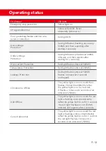
Page 20: ...ellow light on Red light on Please find below for reference LED light instructions EV Charger No Power Power ON Checking Stayby Plug the connector without swiping RFID not ready to charge LED light LED OFF Plug the connector without swiping RFID ready to charge Green Yellow Red Lights ON and OFF Green Light ON Streaming light runs back and forth Streaming light runs fast back and forth Plug the co...

Page 21: ...shes interval 500MS Red light flashes interval 200MS Red light flashes interval 500MS flashes 3 times wait 2 seconds and repeat LED board is Offline The yellow light is on once and then flashes 2 times intermittently after the yellow light is on for 1second it flashes 2 times and 2 seconds at an interval of 250MS DLB Offline Current abnormal The yellow light is on once and the red light is flashin...

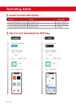
Page 22: ... sound Status Operating Swipe to start Swipe to quit Swipe failure Start charging Stop charging NONE Open Google Play Click Search bar Input Z BOX Z BOX Z BOX Find Z BOX APP Click Download Open APP Store Click Search bar Input Z BOX Click Download Start to use Download the APP here Z BOX Z BOX Find Z BOX APP Android IOS ...

Page 23: ...s no high voltage in the system and then repair the charger Ensure that the emergency stop circuit breaker and other components of the product can be used under any circumstances and conduct regular tests Regularly check whether the product is damaged Warranty description The user s improper handling installation incorrect use and maintenance negligence or natural damage to the product and failure...

Page 24: ...re is any it should be cleaned up in time othewise there is a risk of fire Use risk notification Please confirm whether the parameters of the electric vehicle and the charging equipment match before use otherwise it may cause damage to the vehicle lt is strictly forbidden to use the charger in the case of equipment failure Do not operate without authorization when the charging is abnormal lf you f...

Page 25: ...Changjiang Rd Wenzhou Daqiao Industry Park Beibaixiang Town Yueqing Wenzhou City Zhejiang Province China 325600 VERSION 20211123 For the latest version of specification please refer to www beny com or contact to benyi zjbeny com We reserve the right to explain the terms of specification ...

Reviews: