27
Installation instructions
805845UK v1.02 July 2018 - G4 Command Centre
Technical support
Tel: 0345 6 005 005 Email: [email protected] www.zipwater.co.uk
Section 5 Water block installation
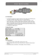
5.1 Description
• The Water Block is designed to be installed upstream of any Zip product and associated pipe-work
to minimise the potential for water leakage in the event of a system malfunction.
• The Water Block is ideal for limiting potential leakage and resulting water damage from water
heaters, water chillers etc. when fitted in supply pipe work that is subject to mains water pressure.
• Once set, the Water Block will ensure that the volume of water that can flow through at one time is
limited to a pre-determined maximum, providing the flow rate through it exceeds 2 litres per minute.
• The Water Block also incorporates a non-return valve.
• The Water Block is WRAS approved.
5.2 Specification
5.3 Precautions
• The Water Block will help to contain leakage exceeding a rate of 2 l/min.
• Note
The leakage at lower flow rates may not be detected by the Water Block and could remain
unchecked.
• Appropriate measures should be taken to contain leakage in these circumstances.
Flow control range
5 - 50 litres
Minimum / Maximum pressure
0.2 - 10.0 bar
Maximum ambient temperature
40ºC
Maximum water temperature
70ºC
Minimum operating flow rate
1.5 +/- 0.5 litres / min.
Inlet connection
¾" BSP female or 15mm
Outlet connection
¾" BSP male or 15mm
!

