


Page 18 of 28
804052US v1.27 06.21 CS75 Install Instructions
Section 5
Commissioning
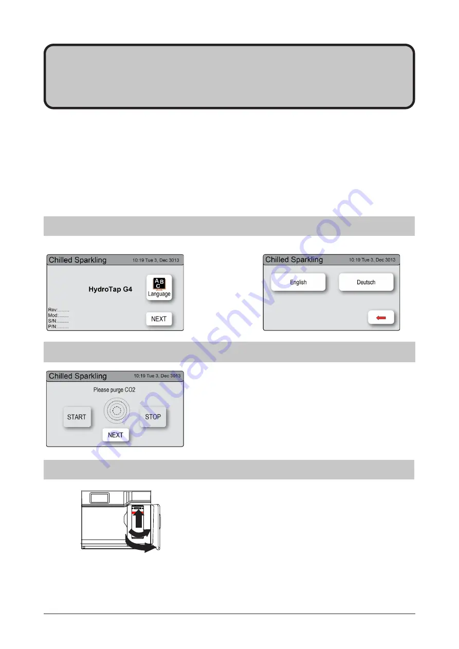
5.2
-
CO
2
Purge
1. Press the [START] button to commence the purging
process.
2. Purge for 10 seconds and ensure all water has stopped
flowing through the faucet. You will hear the CO
2
gas
escaping from the faucet.
3. Press the [Stop] button.
4. Press [Next] for the filter flush screen
The HydroTap is now ready to be commissioned.
•
Turn ON the water and gas and check for any leaks.
•
Turn the power ON at the power outlet and at the side of the Command Center
•
Familiarise yourself with the operation of the Faucet, in preparation for use (See User Manual)
•
Follow the Installation instructions below (and review Section C of the User Manual).
•
Initially you will be prompted to select a language
•
After commissioning, the system may be customised by selecting further options in
Section G - Settings, within the User Manual.
5.1
-
Select the Language
Initial Commissioning screen
Language selection screen
5.3
-
Filter Flush
A new filter cartridge is provided (but NOT fitted), inside the
filter door. Unpack the new filter cartridge and write today’s
date on the label. To install the cartridge, align the key tabs
and insert upwards into the filter head. Turn the cartridge to the
right until it locks in place.
Have a 10 liter (2.6 gallon) bucket or similar container (not
supplied) at the ready to hold a quantity of water that will be
ejected while the Filter Flush Mode is in operation. Open the
filter access door on the front of the HydroTap and the filter
cartridge will be exposed. Located to the rear RHS of the
cartridge is a flush line and the flush line stop cock. Place the
valve end of the flush line into the bucket or container.
1
1
2


