Z8ENCORE000ZAC
Z8 Encore!
®
Smart Cable
UM016207-0508
Page 3 of 6
The power to your design/application board must be turned OFF when
connecting or disconnecting the Smart Cable.
The Smart Cable receives power from the target design/application board.
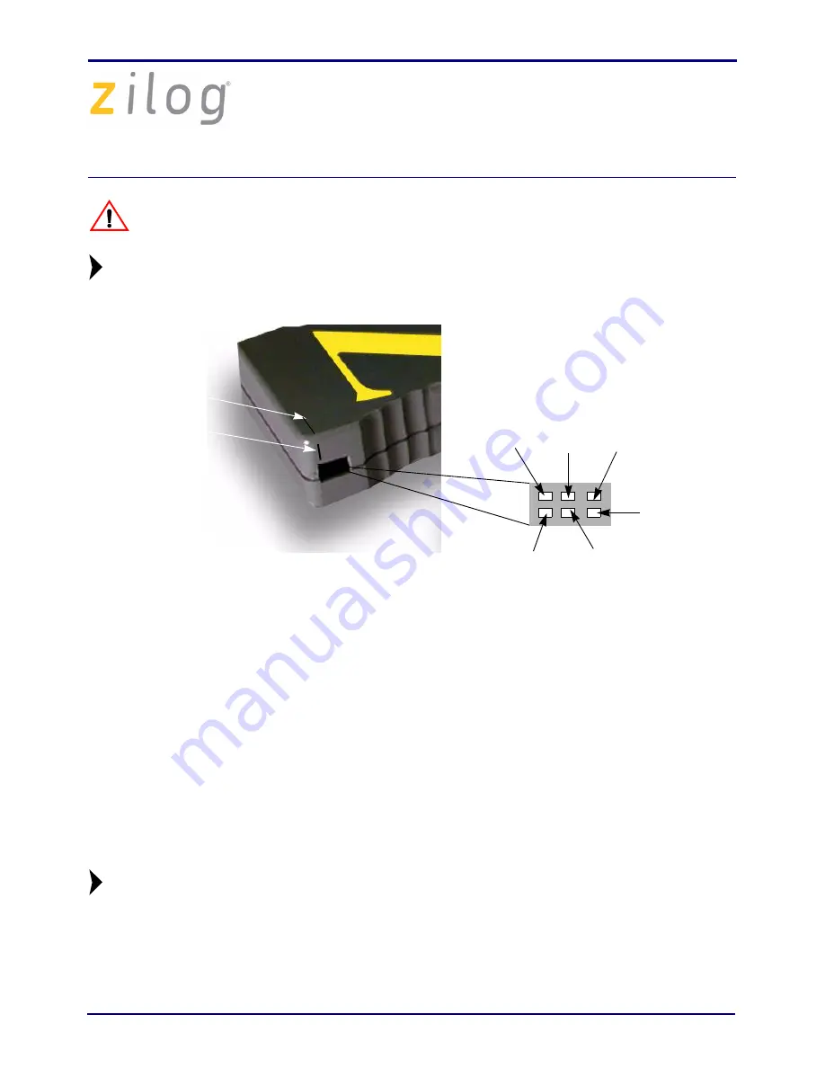
Figure 3. DBG Interface Connector Pin 1 Location
Consider the following points when connecting the Smart Cable to your development
board:
•
The DBG interface connector requires the V
DD
, V
SS
, and the DBG signals from the
Z8 Encore! on your design/application board.
•
The minimum signal connections required to connect the Z8 Encore! to the Smart
Cable are the AV
DD
, V
DD
, AV
SS
, V
SS
, and the DBG pin signals.
•
The AV
DD
must be externally connected to the V
DD
. The AV
SS
must also be
externally connected to the V
SS
.
•
The Z8 Encore! must be clocked to generate the DBG timing signals. For the
recommended crystal oscillator circuit, refer to Product Specification of target MCU.
You must enter the crystal frequency running the Z8 Encore! device when cre-
ating a new project in ZDS II.
Follow the steps below to provide the crystal frequency:
1. Select
Settings
from the
Project
menu.
Caution:
Note:
Pin 1
Pin 5
Pin 6
Pin 3
Pin 2
Pin 4
Groove
Vertical
Horizontal
Groove
Note:


