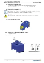
Parts list:
Pos.
Count
Designation
1
1
pre-assembled forced ventilation
2
1
Hexagon head screw ISO 4017 - M12 x 20 - 8.8
3
1
thermostatic switch included insulating tube
4
1
cable tie
The accessories pos. 2, 3 and 4 lie in the terminal box of the pre-assembled forced ventilation (1),
packed in a bag.
8.3.5.3
Mounting of the thermostatic switch
1. Screw the thermostatic switch (3) with a
tightening torque of 3 Nm
into the intended thread (A).
A exceeding of the tightening torque leads to the damage of the thermostat switch.
8.3.5.4
Mounting of the forced ventilation
1. Unscrew eye bolt M12 (B) from the housing.
2. Fasten the pre-mounted forced ventilation (1) onto the motor housing with hexagon head screw
M12 x 20 - 8.8 (2) and eye bolt M12 (B).
3. Feed the insulating hose of the thermostat into the terminal box.
4. Attach the cable tie as strain relief.
Translation of the original operating instructions
ZAtop
–
model series SM210.60B/SM210.70B
Service and maintenance
A-TBA17_01-GB 2023/46 Index 008Part.-No. 01013389-GB (EU-BD 1014/1)
39/96


