


5.3.4
Mechanical connection conditions
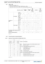
Rated motor current
[A]
Thread size
Terminal board
Thread size
Cable glands
up to 20
M8
M25
> 20 - 35
M8
M32
> 35 - 63
M8
M40
> 63 - 80
M8
M50
> 80 - 100
M10
M50
> 100 - 125
M10
M63
> 125
M12
M63
Table 5-3-4
Permissible tightening torque for M8 bolts: 6 Nm
Permissible tightening torque for M10 bolt: 10 Nm
Permissible tightening torque for M12 bolt: 15.5 Nm
5.3.5
Connection
Danger!
The motor cable must be connected to the correct phase of the frequency inverter and the elevator
machine: U -> U / V -> V / W -> W.
If the actual direction of travel does not correspond to the selected direction, the turning direction of the
elevator machine must be changed in the frequency inverter con
fi
guration. If the motor cable is not
connected to the correct phase, control of the elevator machine is not possible. It can result in jerky
movements or uncontrolled acceleration of the elevator machine.
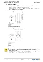
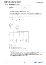
Figure 5-3-5-01
(1) Frequency inverter
(2) Motor temperature monitoring
5.3.6
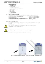
Optimised screening connection
The elevator machine is supplied with an EMC cable gland.
The motor cable shielding must be exposed over a length of at least 10 mm.
The motor cable must be positioned so that the contact springs (2) of the EMC cable gland come into
contact with the exposed range (1). Check the contact with a continuity tester.
Figure 5-3-6-01
(1) Exposed area of the motor cable
(2) Contact springs
Translation of the original operating instructions
ZAtop
–
model series SM210.60B/SM210.70B
Electrical installation
A-TBA17_01-GB 2023/46 Index 008Part.-No. 01013389-GB (EU-BD 1014/1)
16/96