


Note
Note that an overload in the car leads to an increase in the motor torque. 25 % overload results in
150 % of the required motor torque! As regulated elevator machines are normally designed for a
maximum torque of ca. 170 - 200 % rated torque, only slight reserves are available during such
special cases.
Correspondingly, section
6.3.4 "Capture device on the cabin"
in
EN 81-20:2020
must be followed:
“
In order to facilitate disengagement of the safety gear, it is recommended that the test be carried out
opposite a door in order to be able to unload the car.
”
6.5
Emergency evacuation
Attention!
The measures for emergency evacuation described below may only be performed by instructed
persons for maintenance of the elevator or quali
fi
ed personnel of elevator companies.
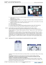
6.5.1
Emergency evacuation by release of the brakes
In case of power failure or failure of the recovery control, emergency rescue is only possible by
releasing the brakes. The brake can be released by an electrical emergency power supply or, if
available, by a manual hand release.
When the brakes are released manually, the elevator moves in the direction of the greater weight. If
there is a balance between the cabin and the counterweight, the cabin must be made heavier by
suitable means.
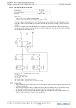
To reduce the acceleration of the elevator, we recommend short-circuiting the motor windings for the
evacuation. The short-circuit is generated by the motor contactors or an electronic circuit, as in the
frequenzy inverter type ZAdyn 4C. This is always e
ff
ective even in the event of a power failure.
The short-circuit generates a speed-dependent braking torque. The maximum braking torque is
achieved at lower speeds.
Depending on the system type and weight ratios, it is possible that due to the short-circuit
generated braking torque is not su
ffi
cient to limit the lift speed. So the speed must be
monitored closely during evacuation and evacuation interrupted if necessary.
Releasing of the brake can be ended when a
fl
oor is reached. Now the elevator door can be opened
with a triangular key.
The elevator manufacturer's safety instructions have priority!
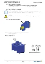
6.5.2
Releasing of the brake with the lever for hand release
A brake with a mechanical hand release system is available optionally. The hand release system
cannot be
fi
tted later. The complete brake must be replaced to retro
fi
t the hand release system.
The brake circuits can be released separately from each other with a mechanical hand release
system.
The levers for hand release can each be attached with an o
ff
set of 90
°
.
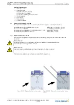
Figures 6-5-2-01
Possible insertion positions
of the levers for hand release
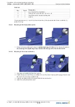
Figures 6-5-2-02
Brake not opened
Example for hand release lever position
Figures 6-5-2-03
Brake manuell released
Example for hand release lever position
"
"
Attach the levers for hand release to the brake in any position.
"
"
The brake is released via simultaneous movement of both levers for hand release. The direction is
not of any signi
fi
cance in this regard.
Translation of the original operating instructions
ZAtop
–
model series SM210.60B/SM210.70B
Commissioning
A-TBA17_01-GB 2023/46 Index 008Part.-No. 01013389-GB (EU-BD 1014/1)
25/96